 MIKE MCGLOTHLIN
.
December 30, 2020
.
c10
.
MIKE MCGLOTHLIN
.
December 30, 2020
.
c10
.
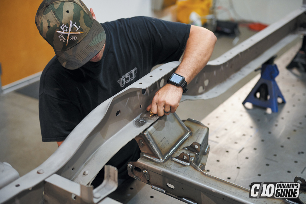
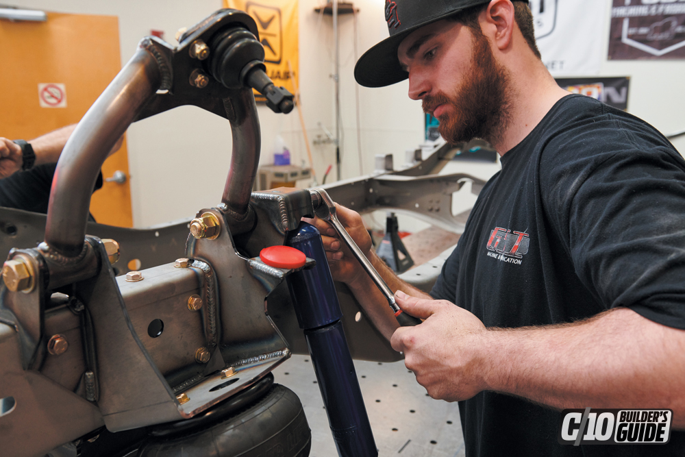
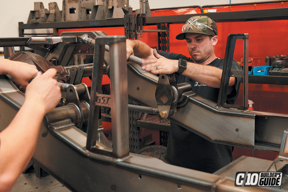
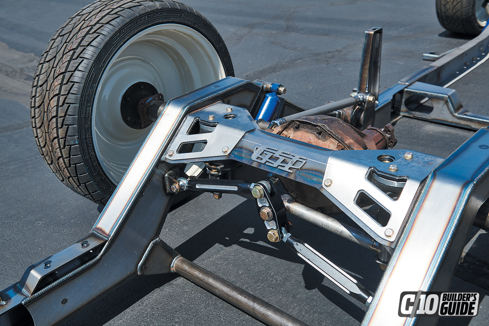
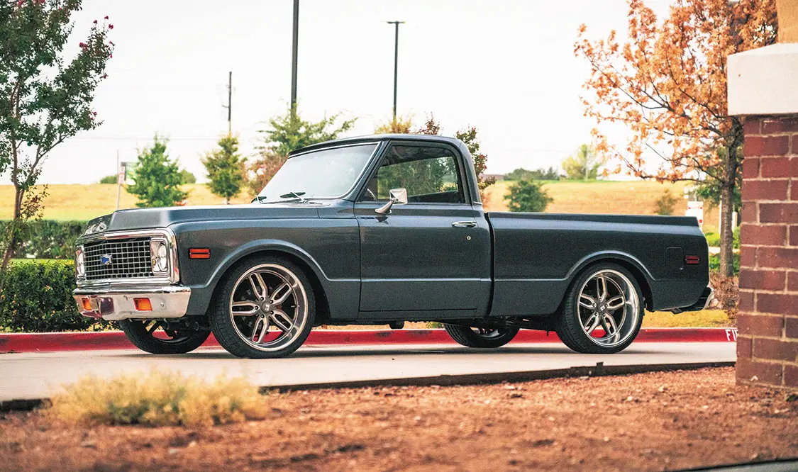
So, you bought an old C10 and you just don’t love the stance? Let me guess—you want it “hammered on the ground, but still enjoyable to drive.” Confidence and driveability in your air suspension are what you need. If you’re looking to put air ride suspension on a classic ’63-’87 C10 but want to make sure you are satisfied after all the time and money spent to get there, consider this GSI Machine and Fabrication C10 frontend suspension kit.
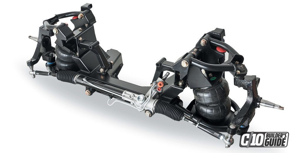
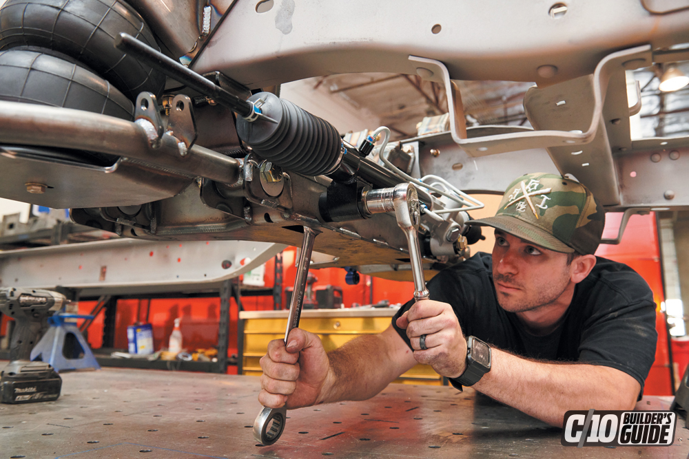
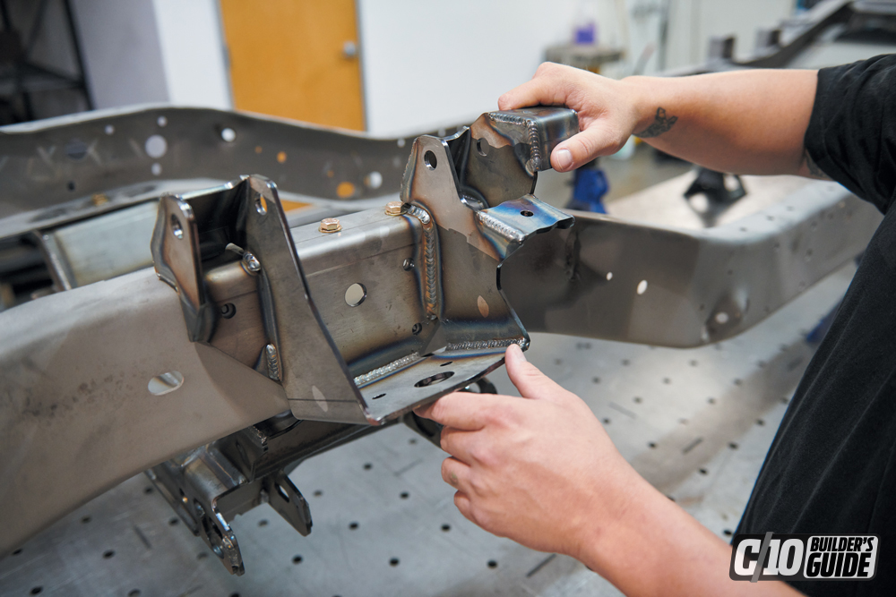
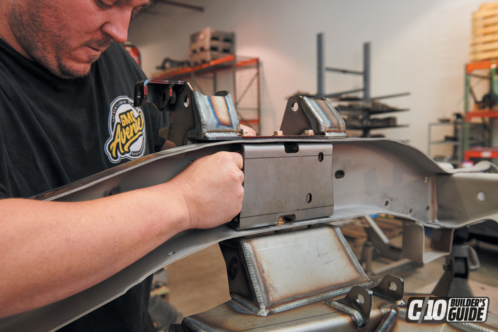
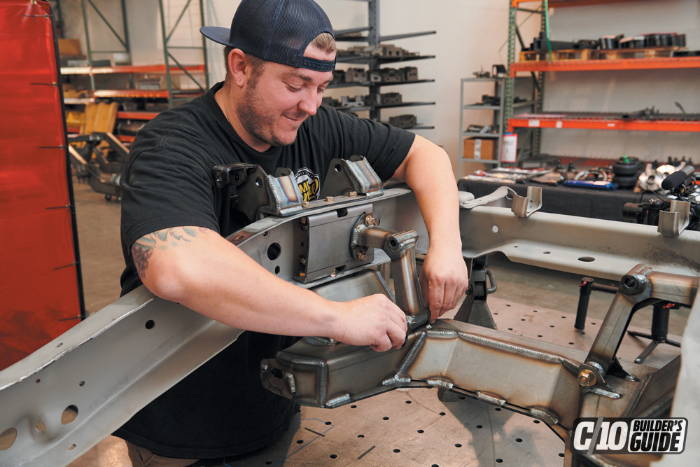
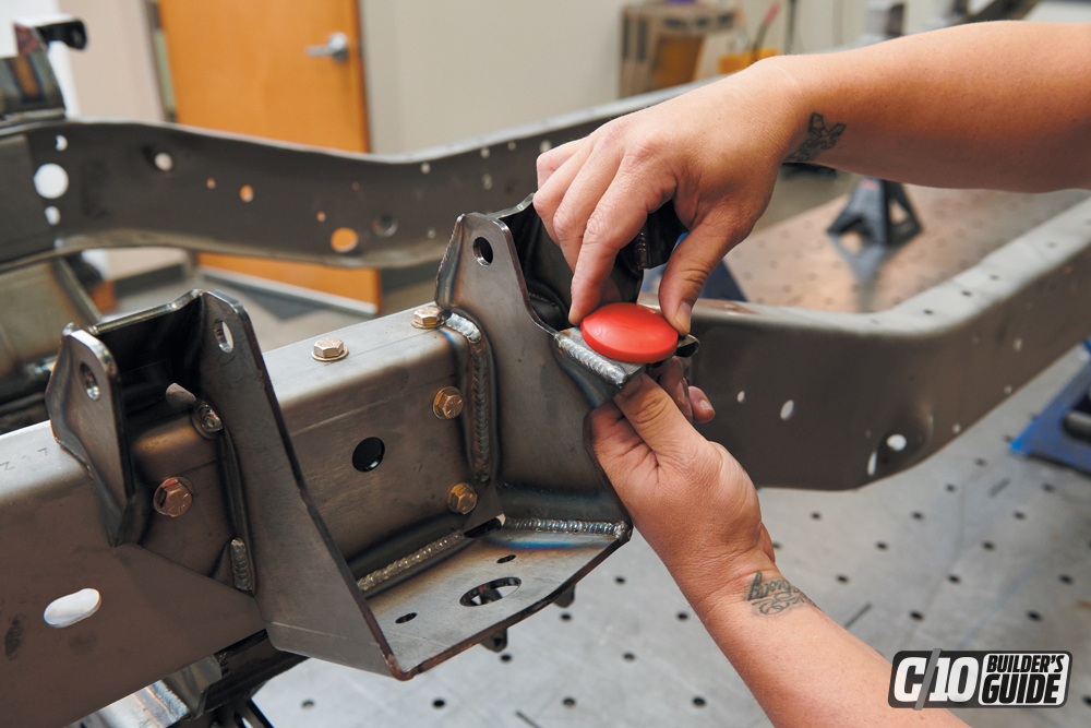
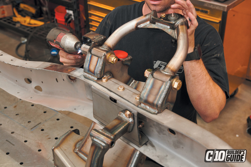
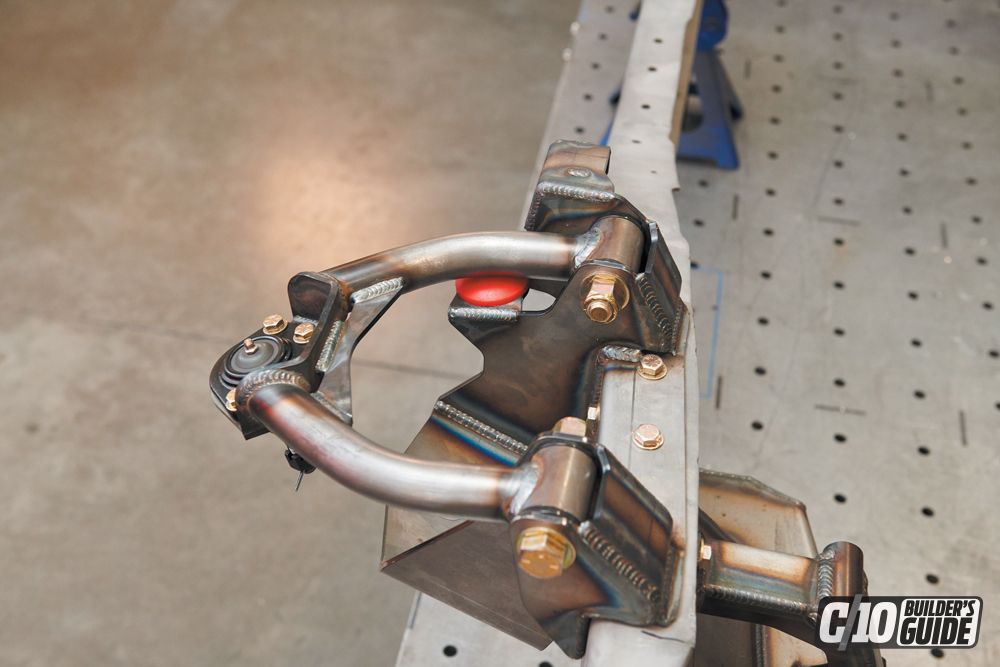
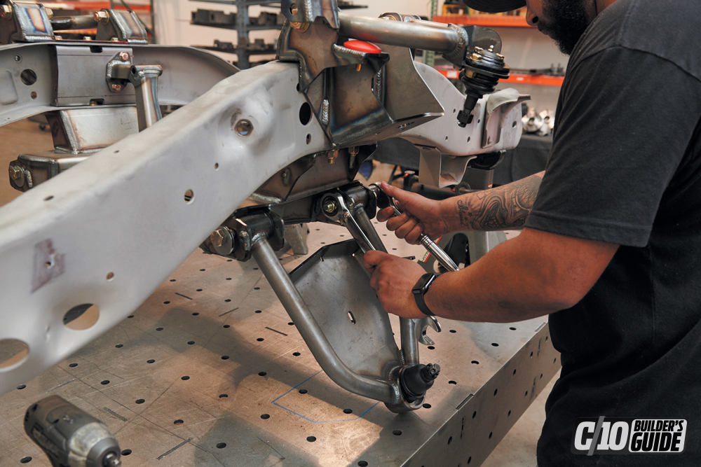
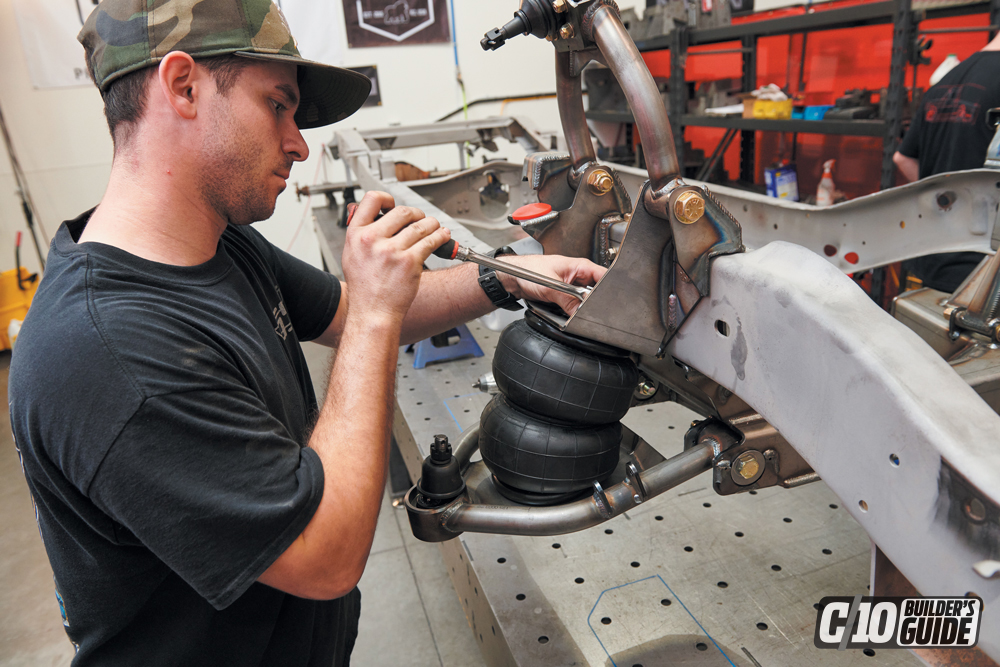
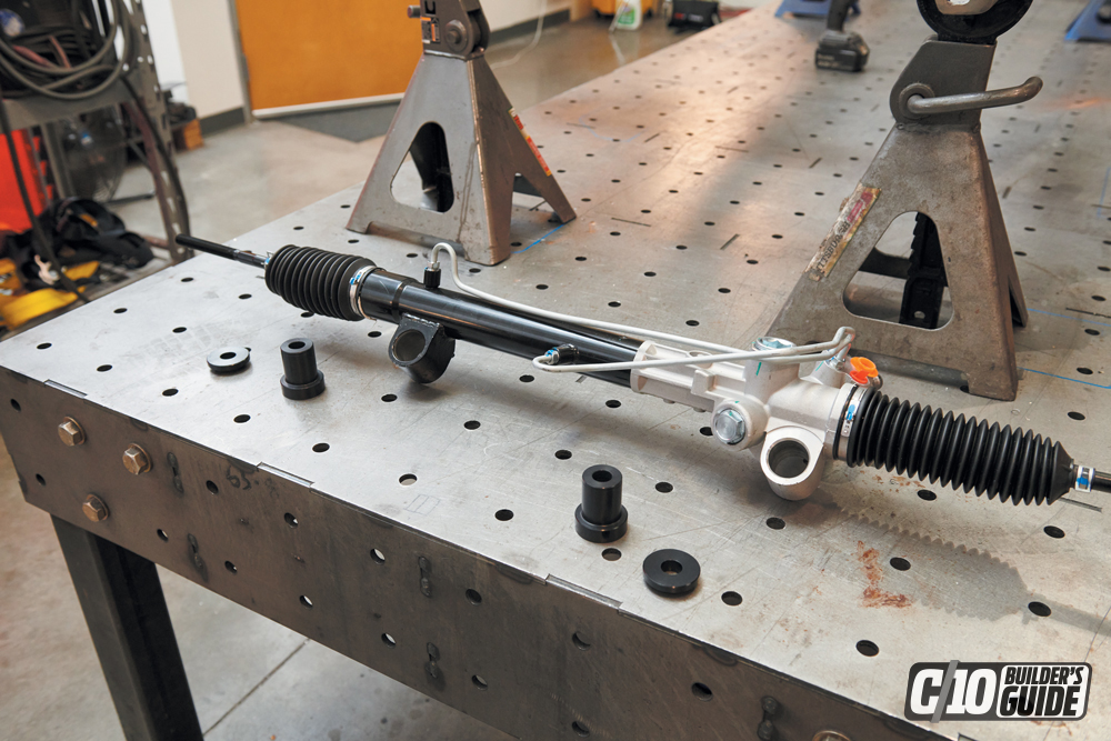
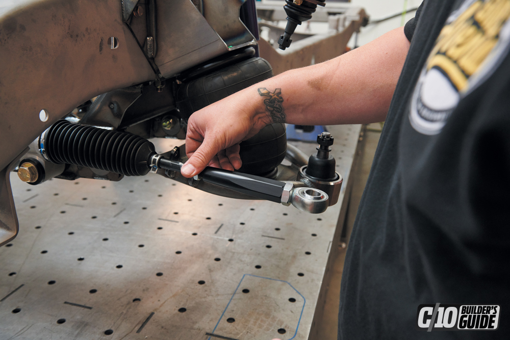
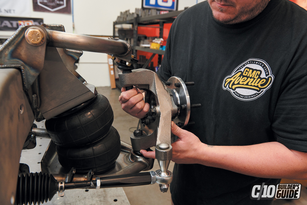
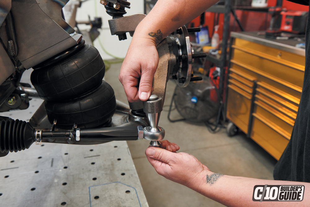
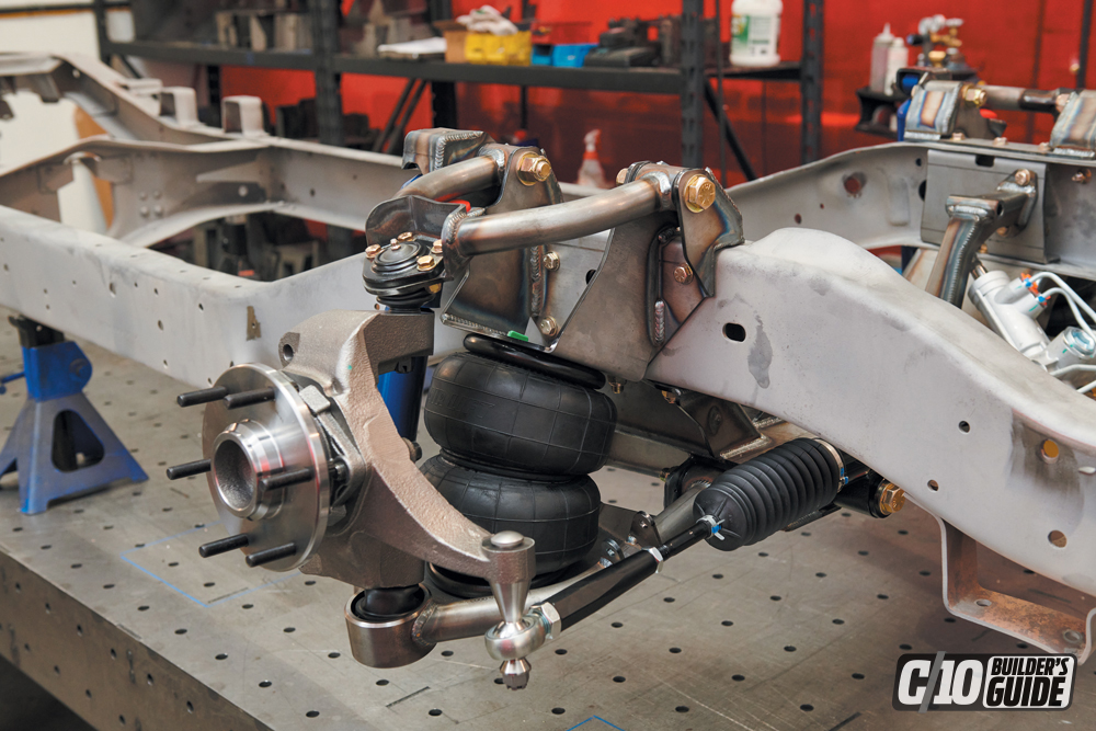
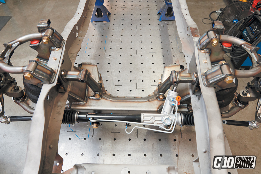
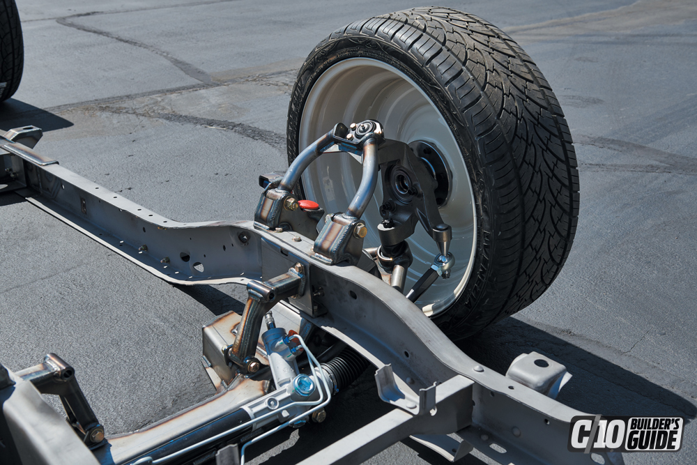
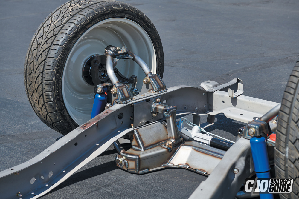
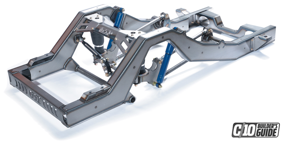
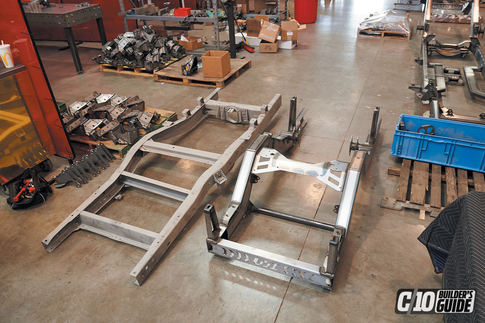
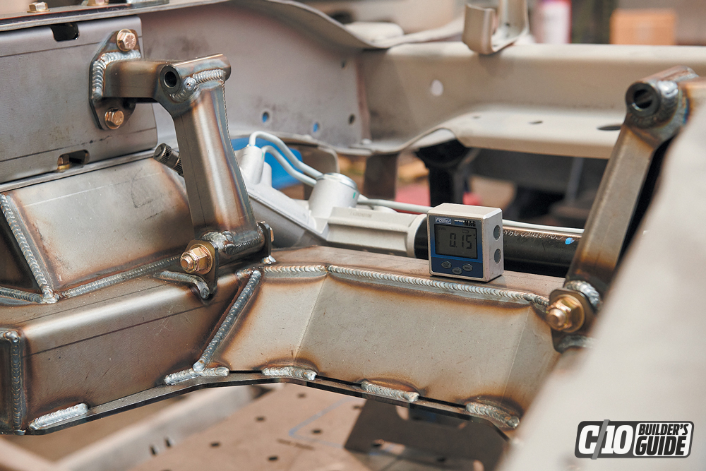
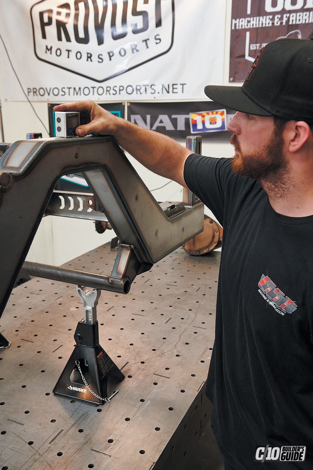
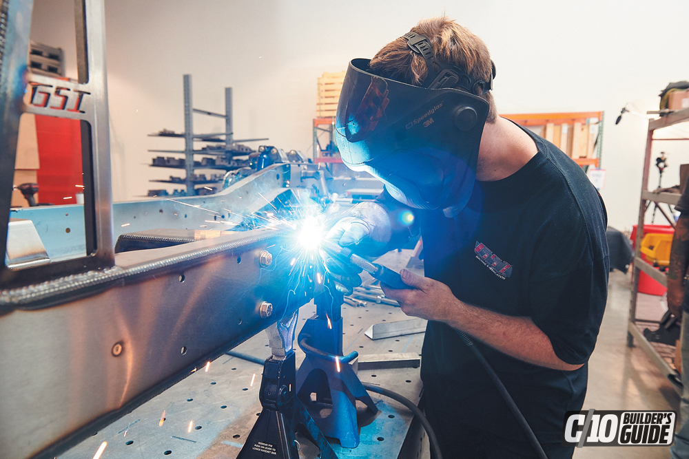
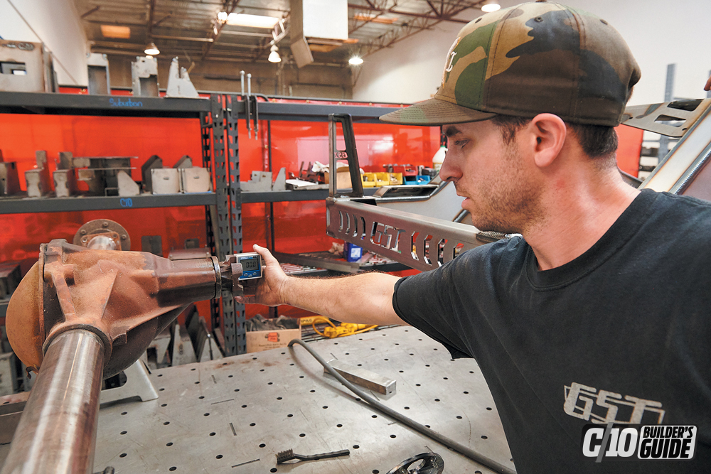
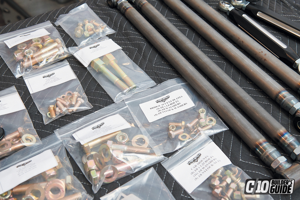
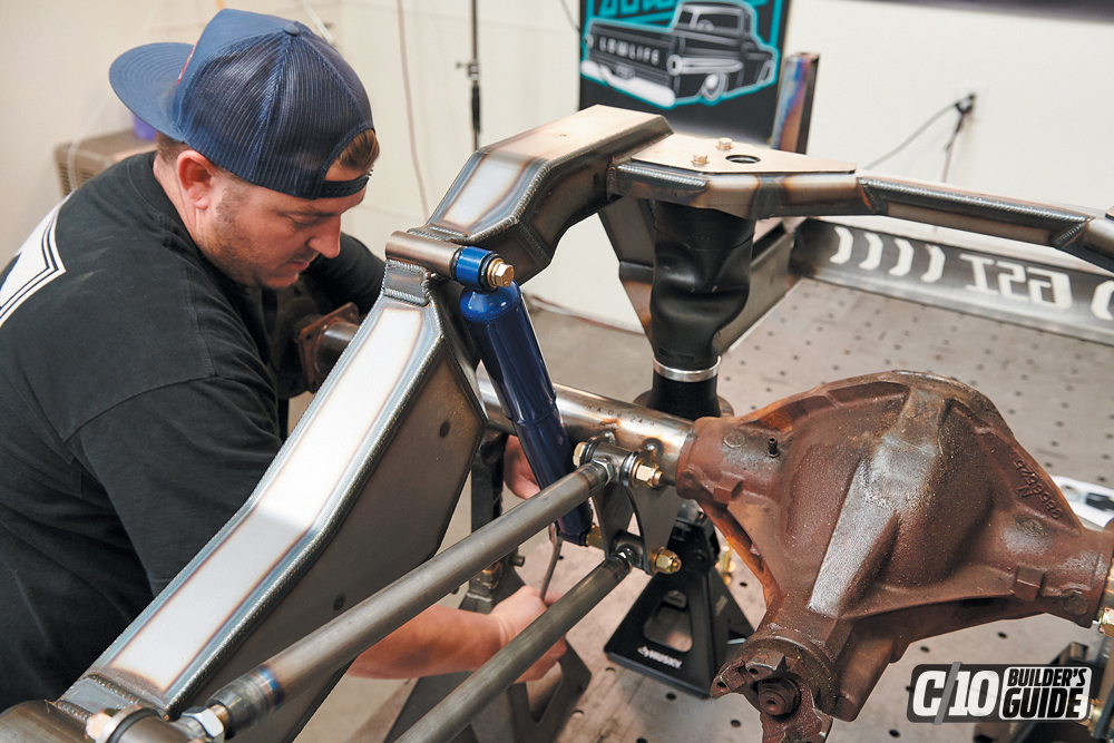
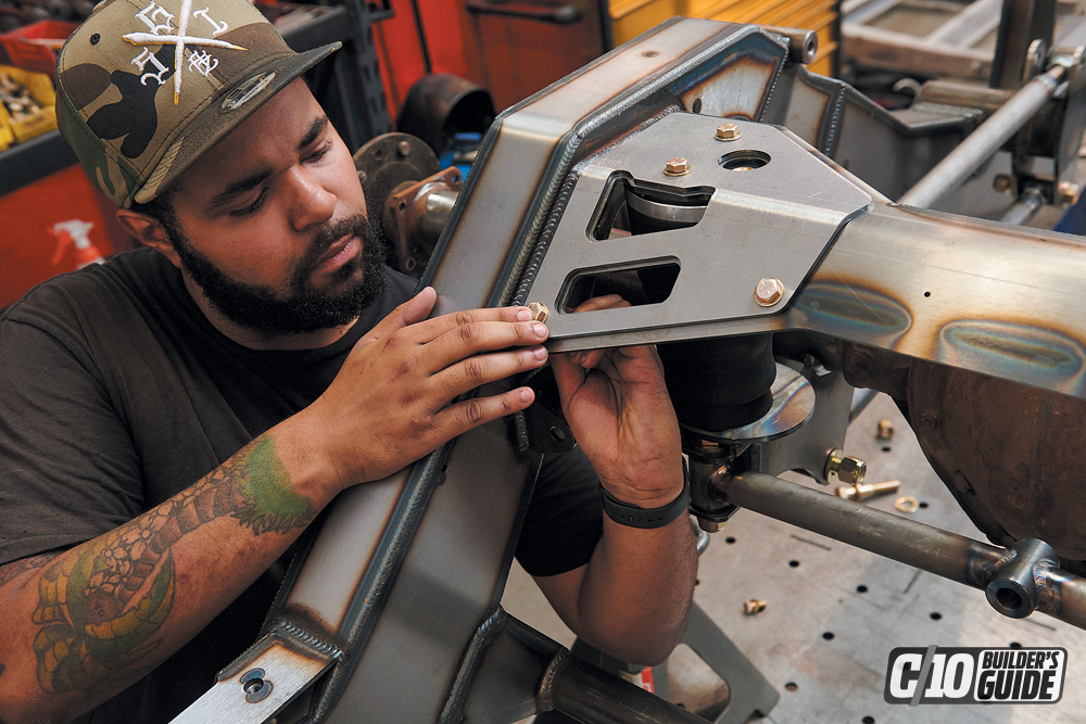
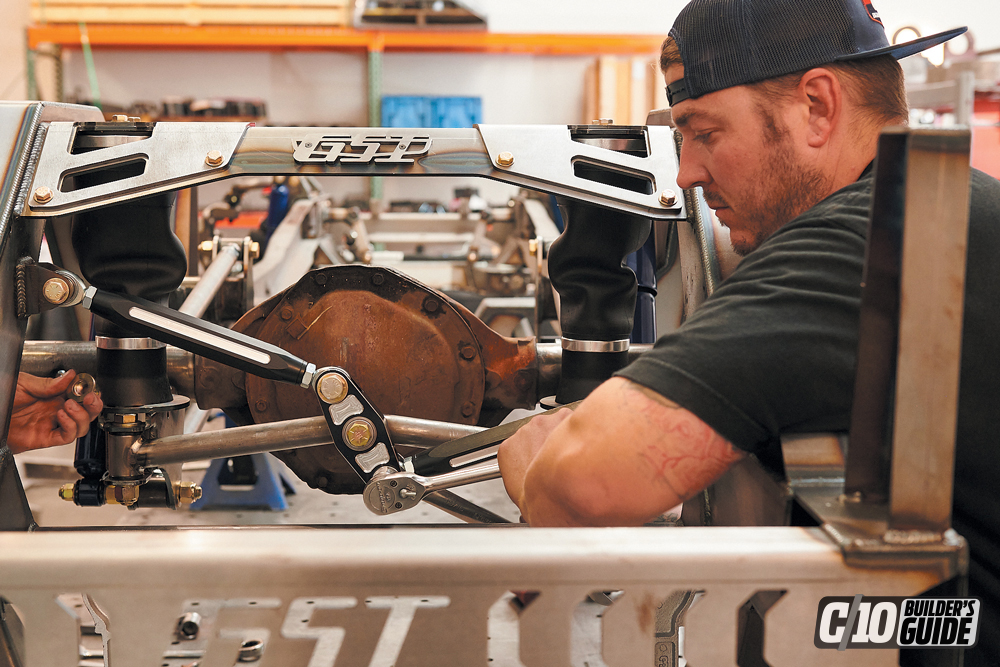
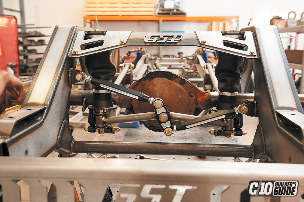
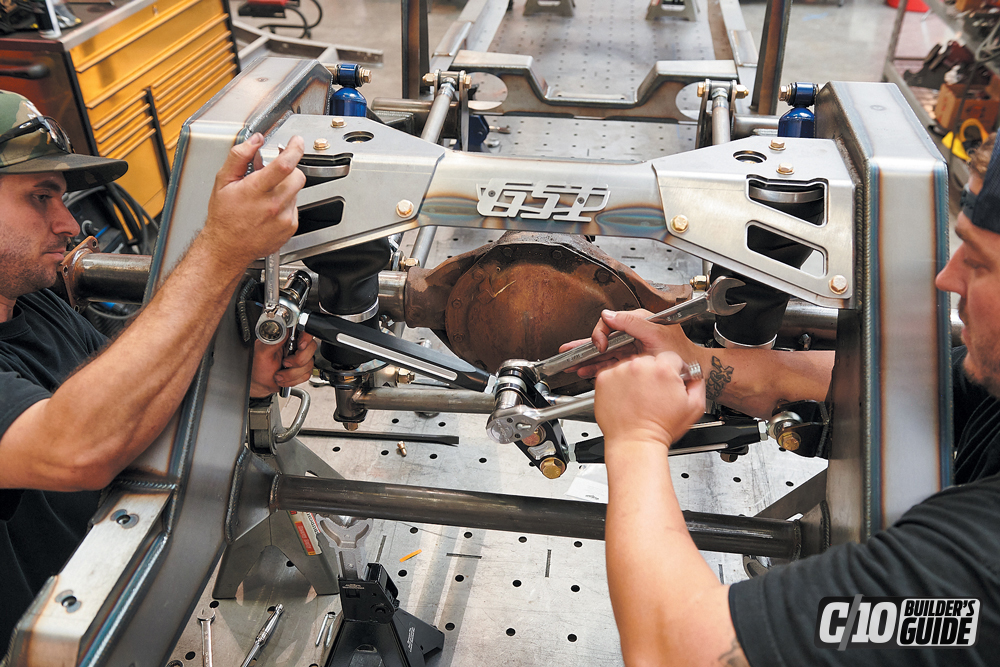
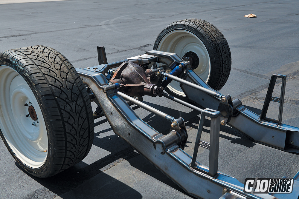
This superior geometry specifically designed for a stock C10 chassis with airbags, this kit accepts large-diameter wheels and tires up to 31 inches tall. This kit narrows the track width, making wheel options greater, and brings the cross-member and lower control arm pivots up out of the way so your frame rails lay flat on the ground when aired out. This system also upgrades the steering to a power rack-and-pinion unit and utilizes disc brake spindles, which are all supplied by GSI when you order the complete kit.
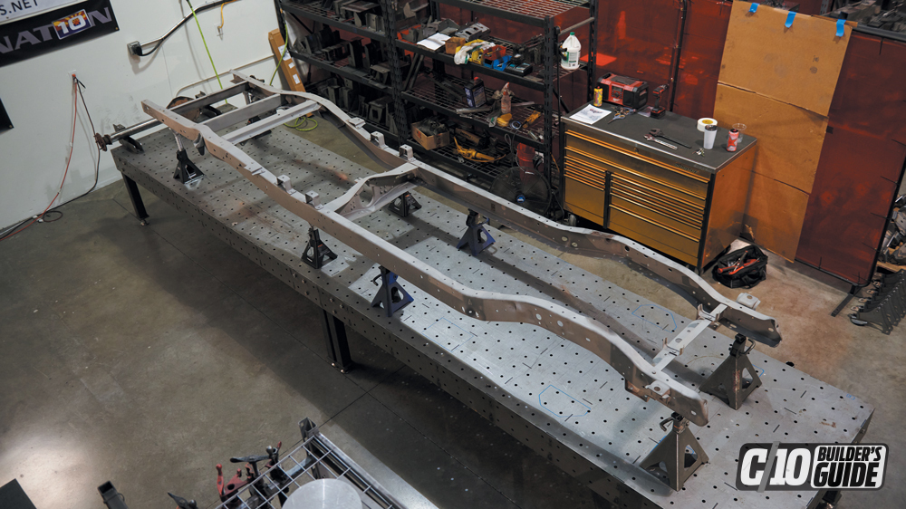
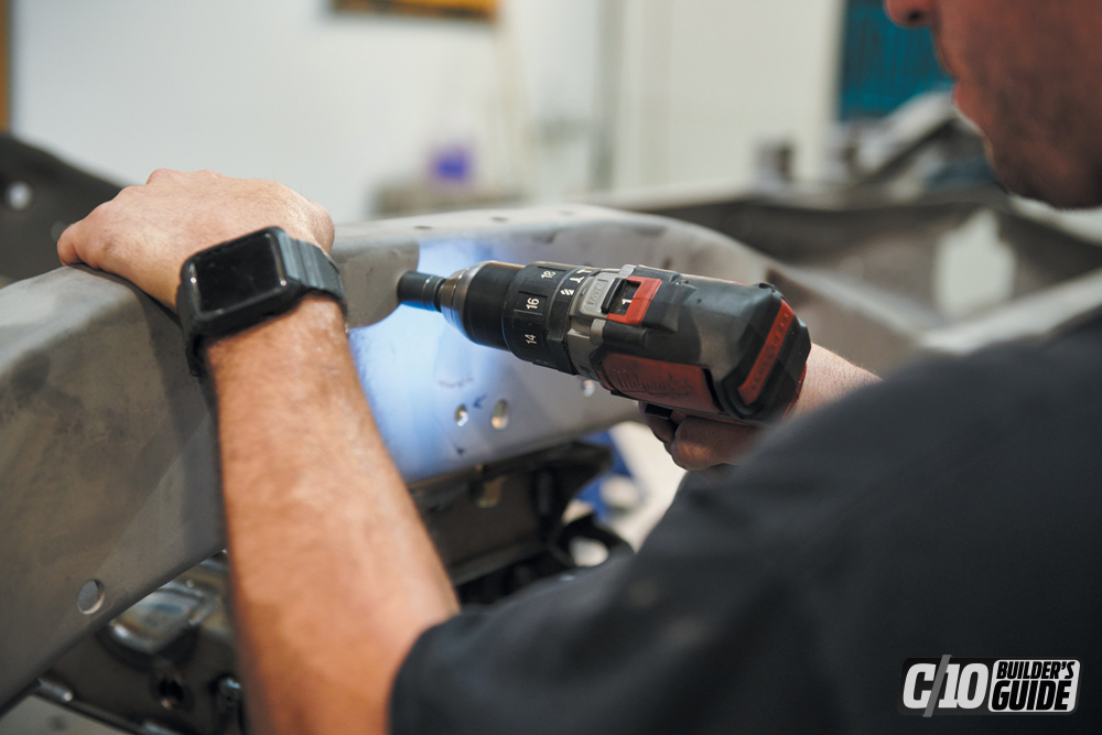
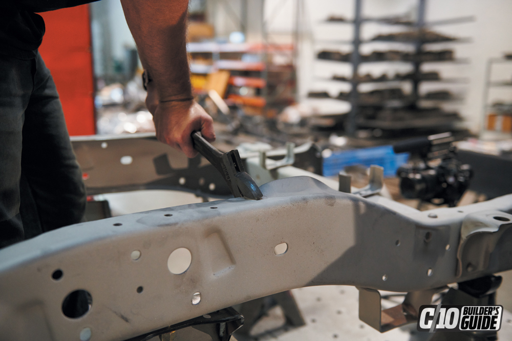
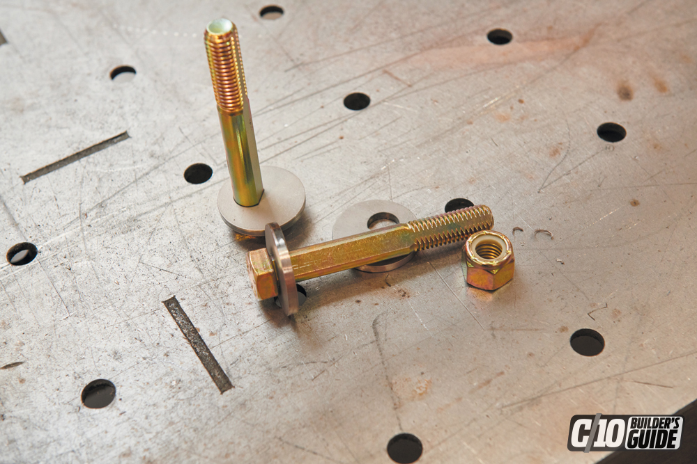
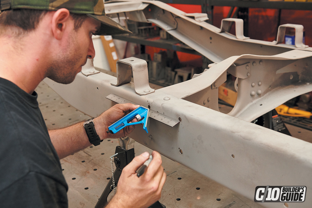
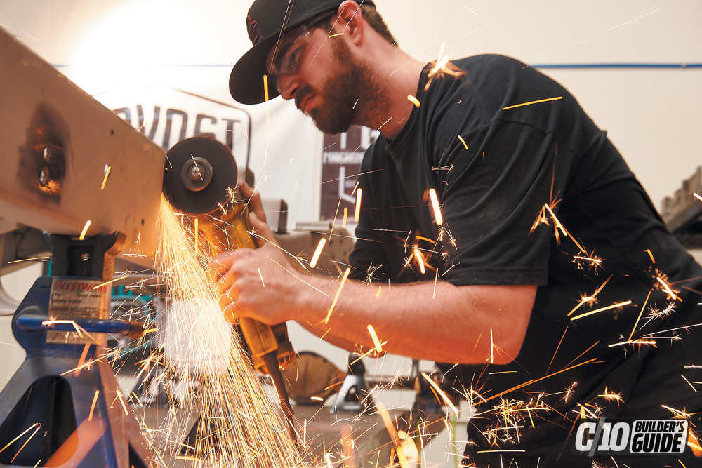
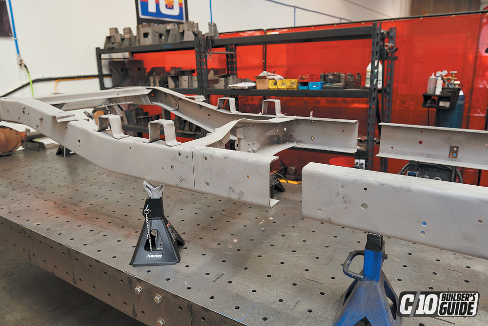
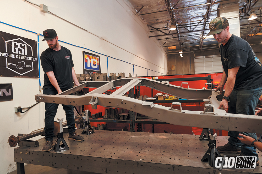
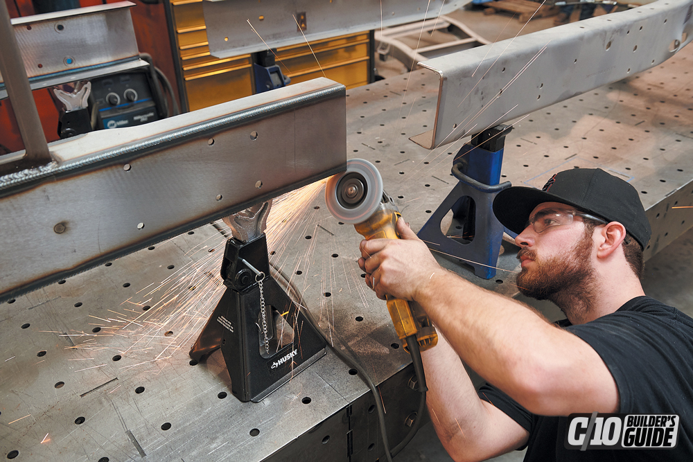
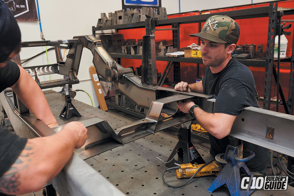
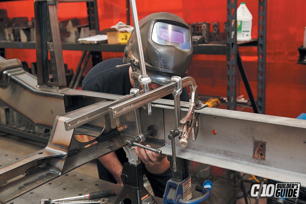
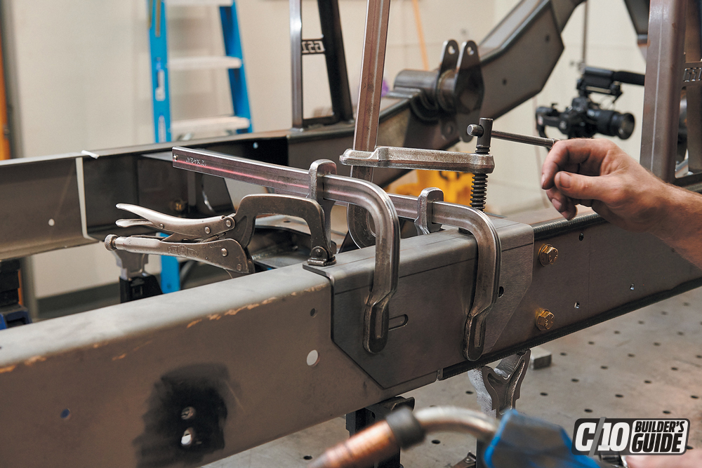
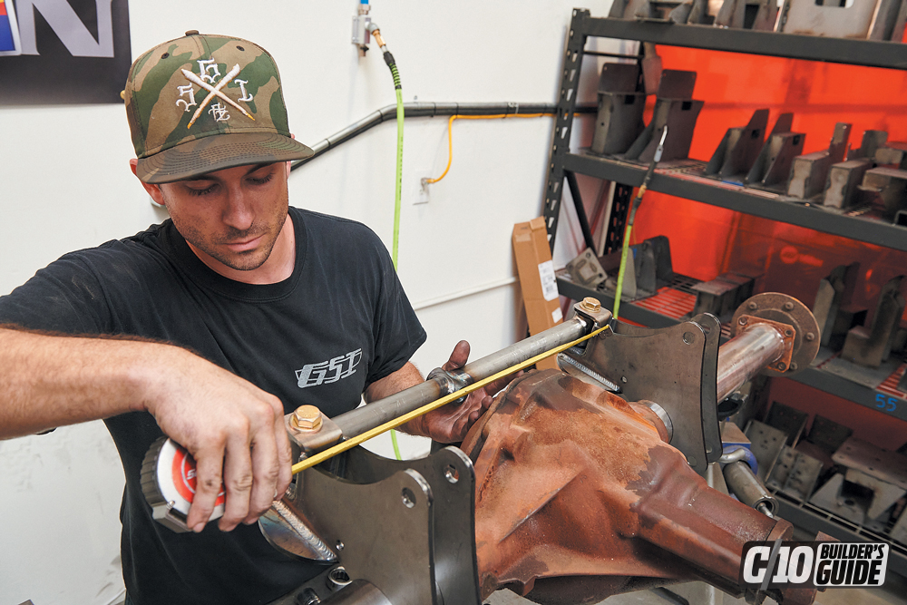
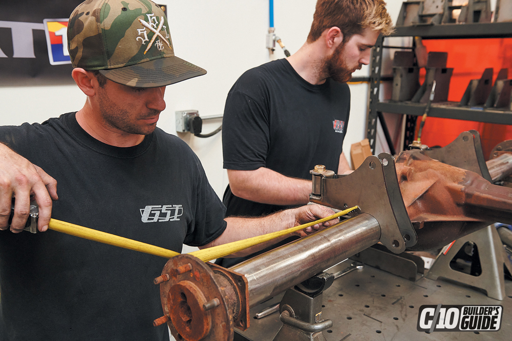
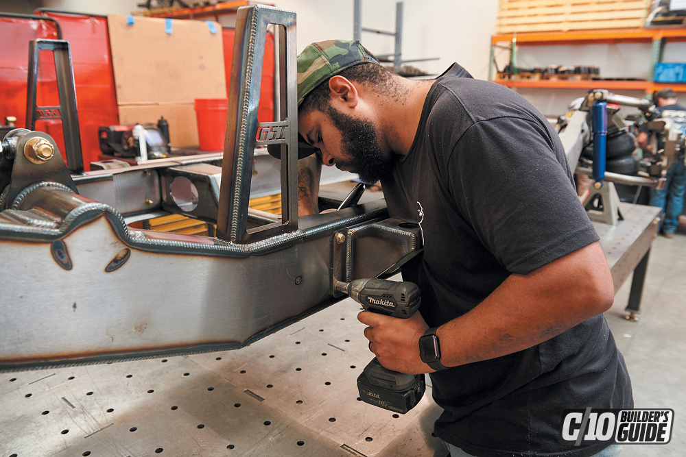
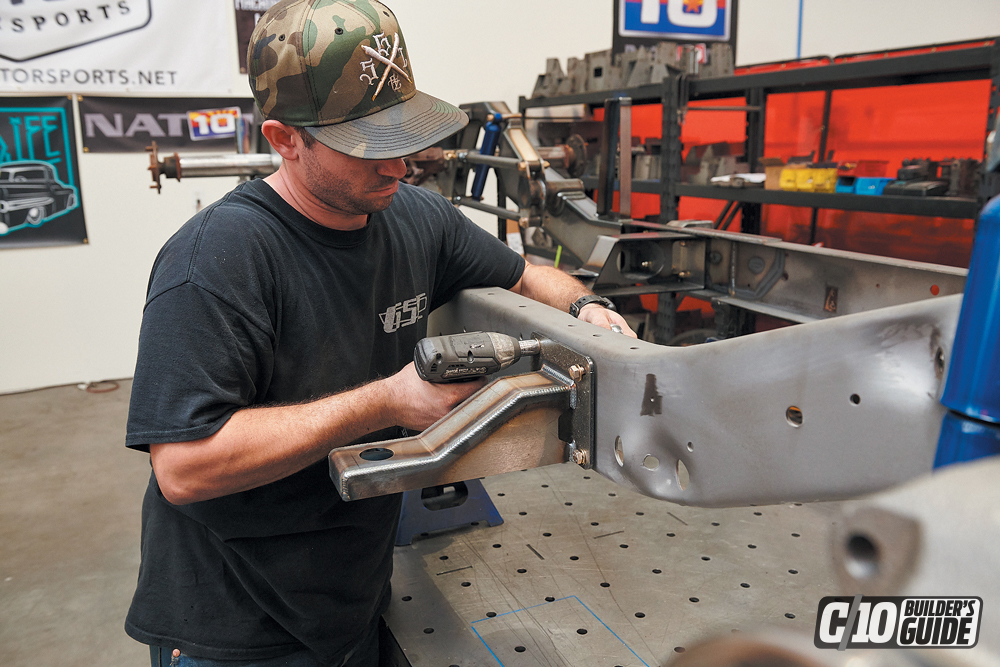
We grabbed a longbed ’64 stock chassis, stripped it down to its bare bones and had it sandblasted by Matador Powder Coating in Mesa, Arizona. When we got the frame back, we brought it to our fab shop and set it on the frame table. This install can be done without the use of specialty tools. You will need a press for the ball joints and bushings, but otherwise a floor jack, sockets, ratchets, wrenches, a couple of jack stands and a drill will get it done.


Department
“The great John O’Neill came through with another amazing cover shot. This time it’s a C-10 with a story you have to read!” FEATURESGone Green –… Continue reading
Chris Hamilton . September 21, 2020
C10 Builders Guide
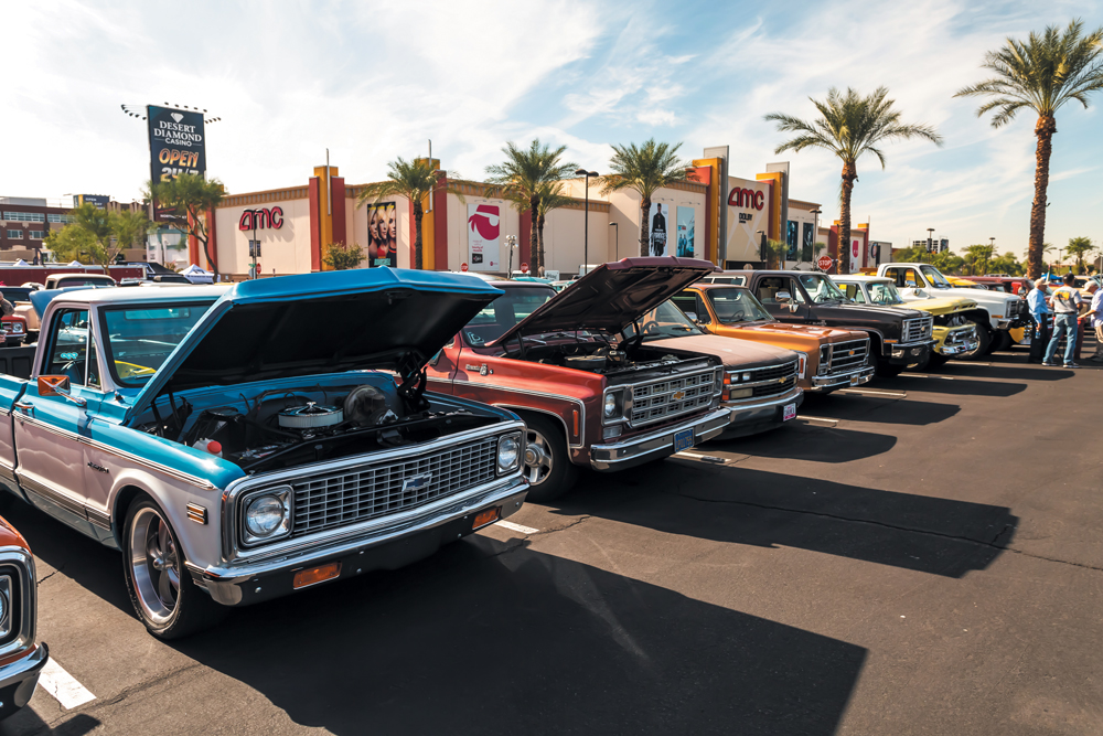
The 2019 Git Down brought out 1,620 Chevrolet/GMC trucks from all over the U.S. How impressive is that? If you happened to be one of… Continue reading
Chris Hamilton . May 14, 2020
C10 Builders Guide
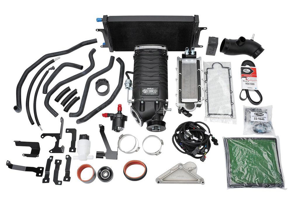
Colorado/Canyon Supercharger Kits Edelbrock E-Force Colorado/Canyon Stage 1 street-legal supercharger kits are exclusively tailored to boost the performance of your popular midsized truck. If you… Continue reading
Chris Hamilton . January 10, 2020
c10
Humble Gathering Grows Again Welcome to C10ville U.S.A., as they say! C10s in the Park was held this year Sept. 16, 2023, with more than… Continue reading
Mike Alexander . December 11, 2023
c10
For a Good Cause The C10 Fall Revival is a classic truck lover’s take on something sort of like a church revival. Beauty, tranquility, good… Continue reading
Mike Alexander . December 13, 2023
C10 Builders Guide
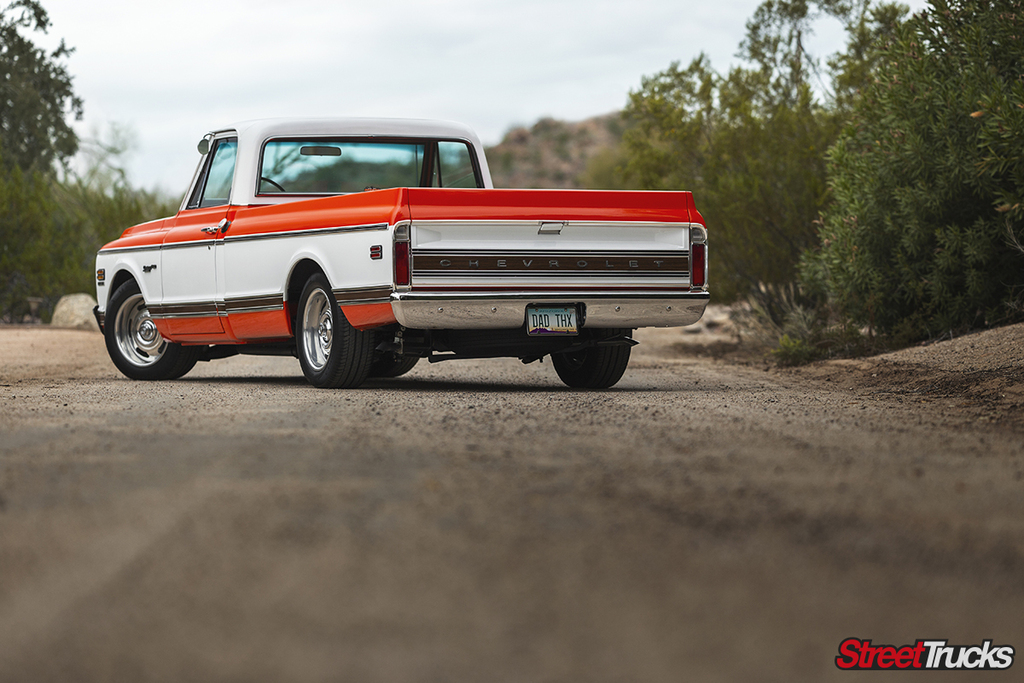
Cruising Through 41 Years in a Big-Block Powered, Long-Bed Bow Tie Beauty Nostalgia. When you have owned a truck for over 40 years it’s… Continue reading
Travis Noack . March 25, 2024


We use cookies to enhance your browsing experience, serve personalized ads or content, and analyze our traffic. By clicking "Accept All", you consent to our use of cookies. Visit our Cookie Policy for more info.
Share Link