 JOSEPH DOWLING
.
June 15, 2020
.
Features
.
JOSEPH DOWLING
.
June 15, 2020
.
Features
.
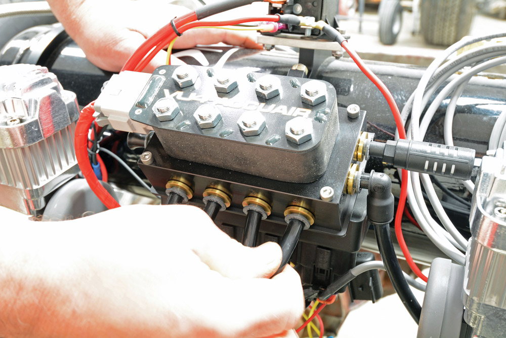
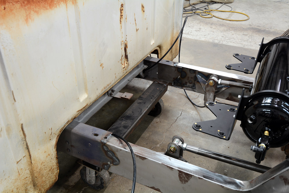
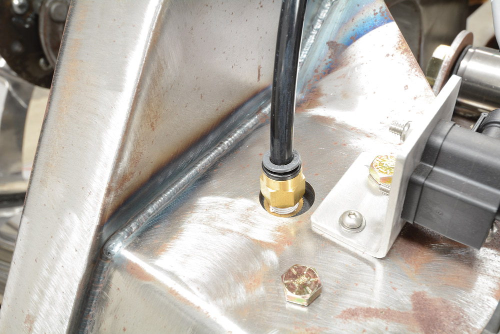
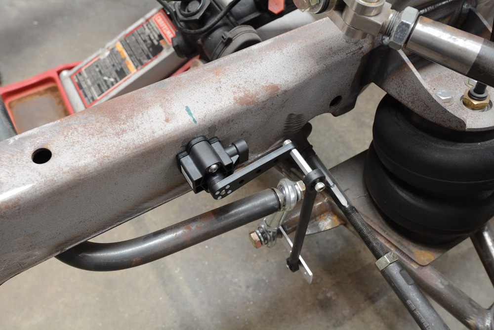
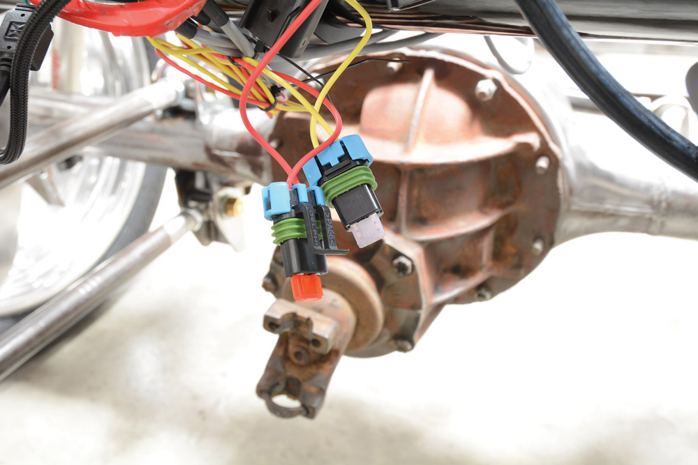
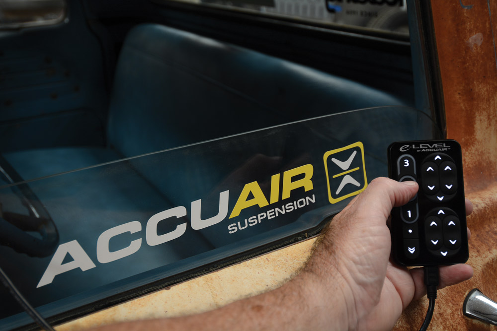
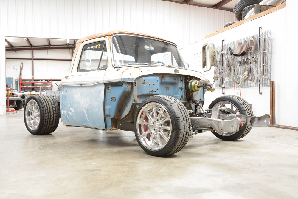
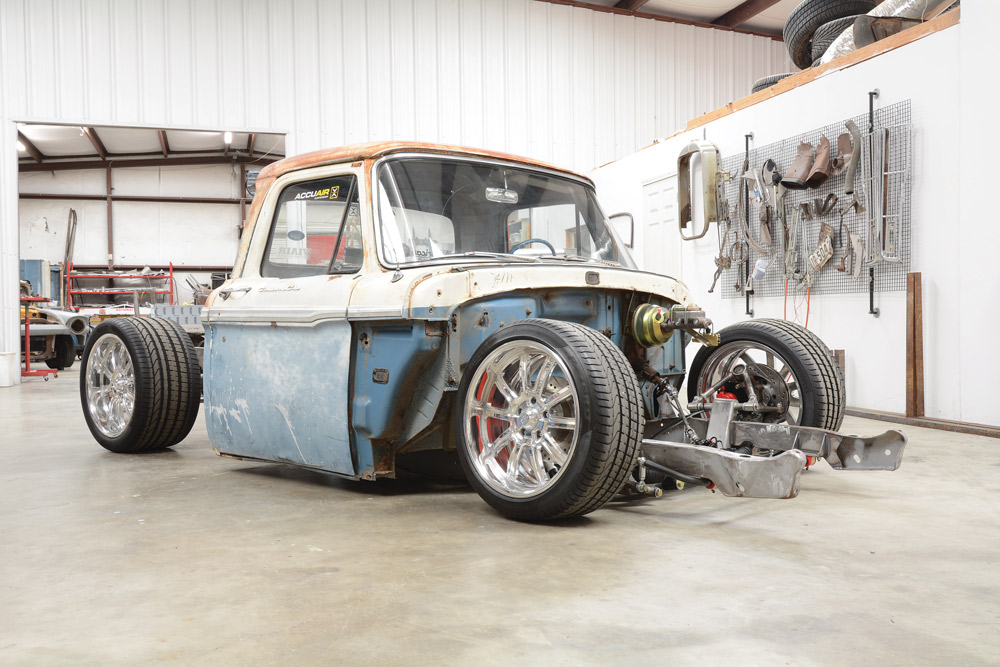
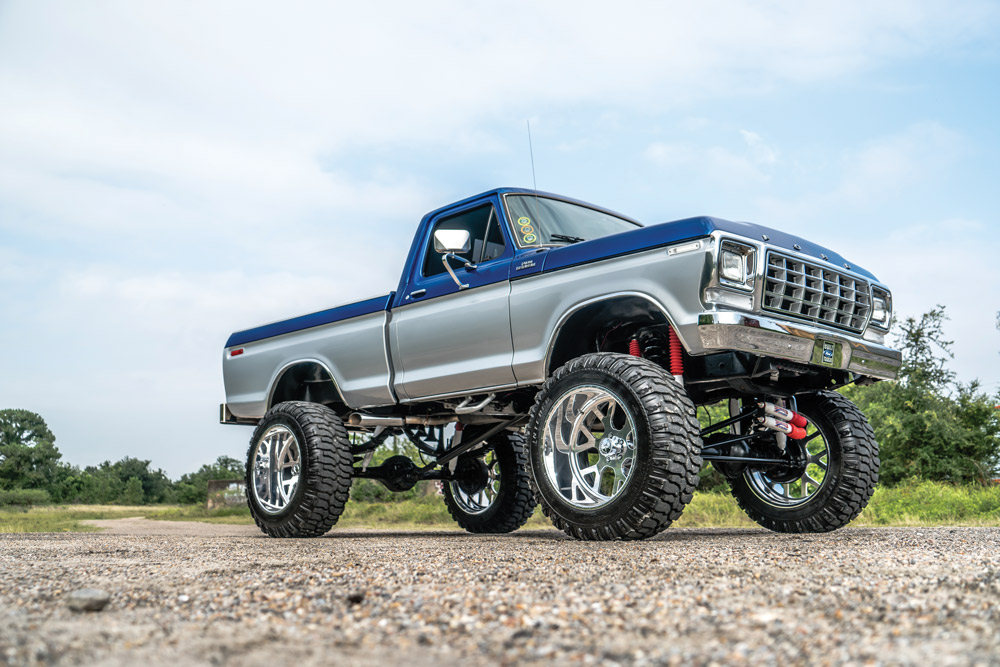
ACCUAIR HAS BECOME A LEADER IN THE air management industry thanks to its dedication to creating quality products. When we were choosing an air management system for our ’65 Ford F-100, we wanted something that was dependable and would require very little maintenance once it was installed. After doing a lot of research we went with the AccuAir E-Level kit. Its three levels of adjustability (raised, ride height and slammed) was the prime reason we were sold on AccuAir.
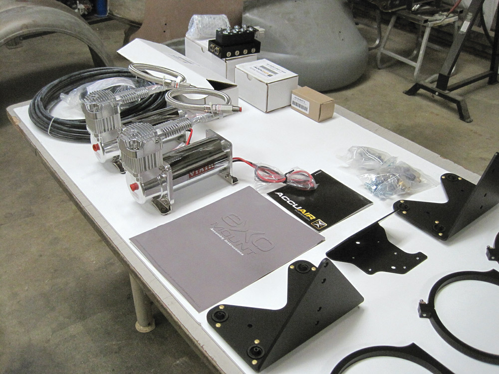
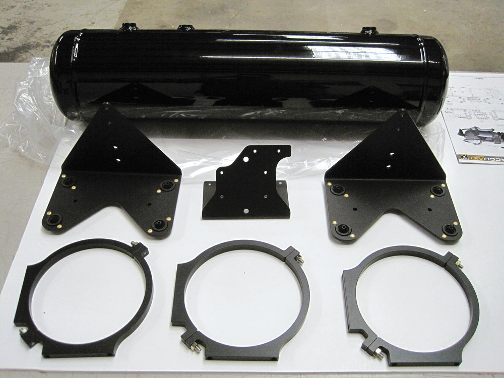
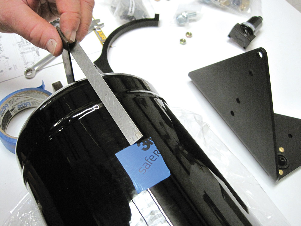
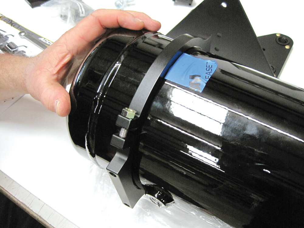
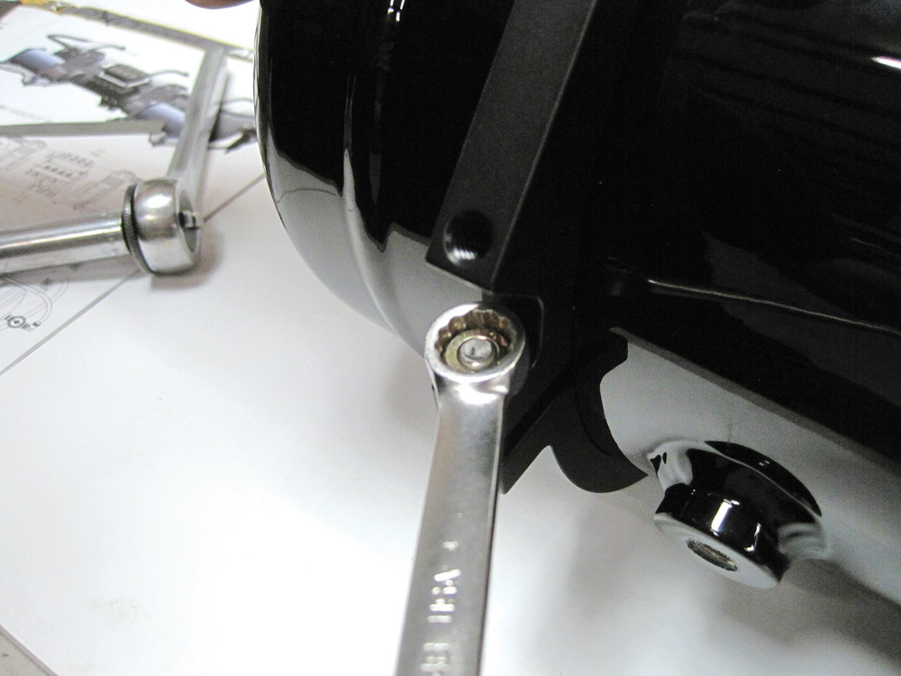
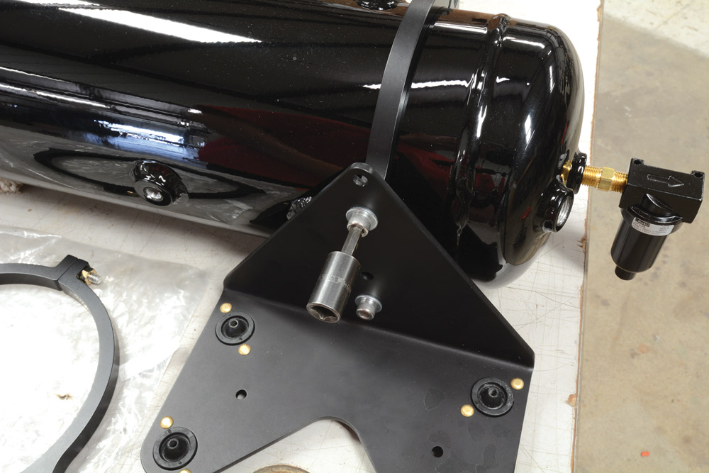
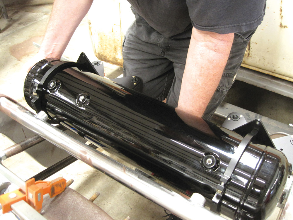
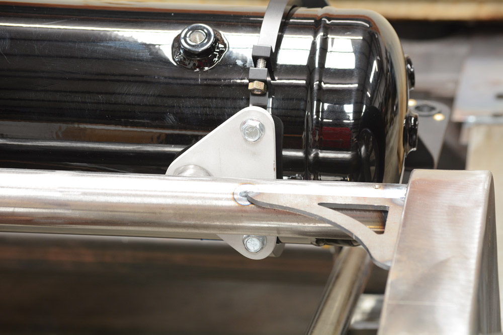
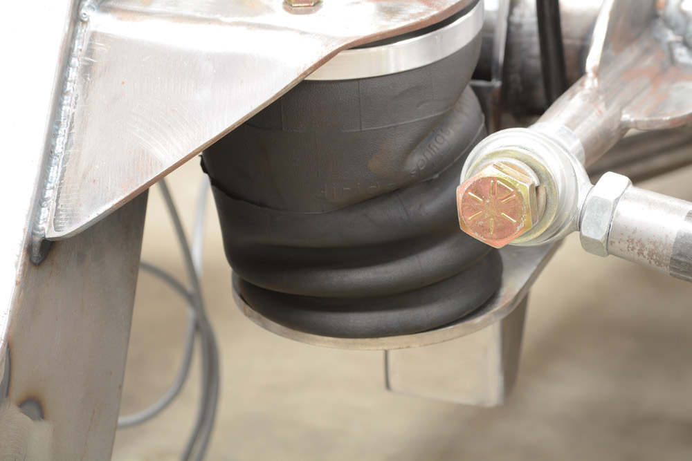
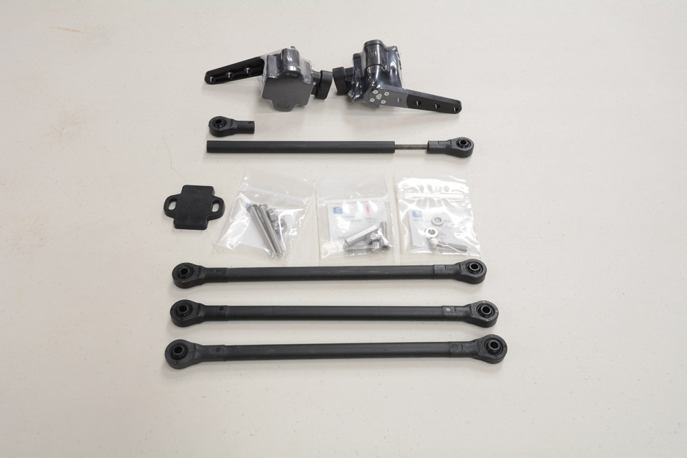
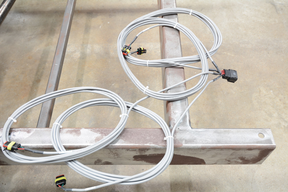
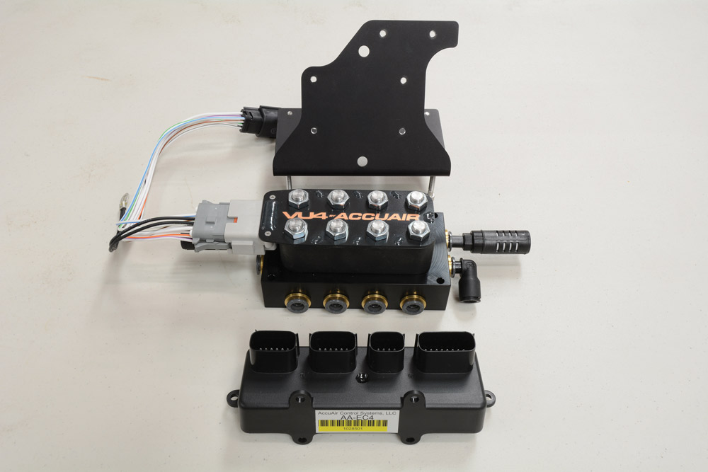
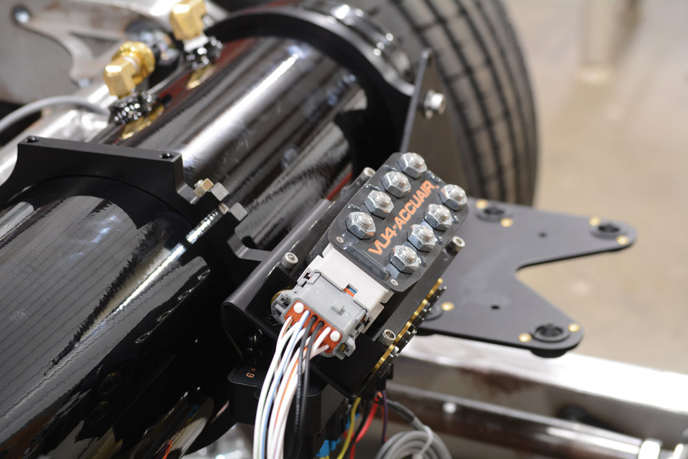
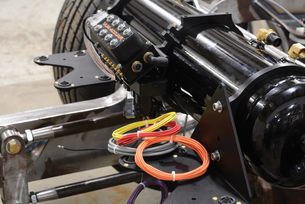
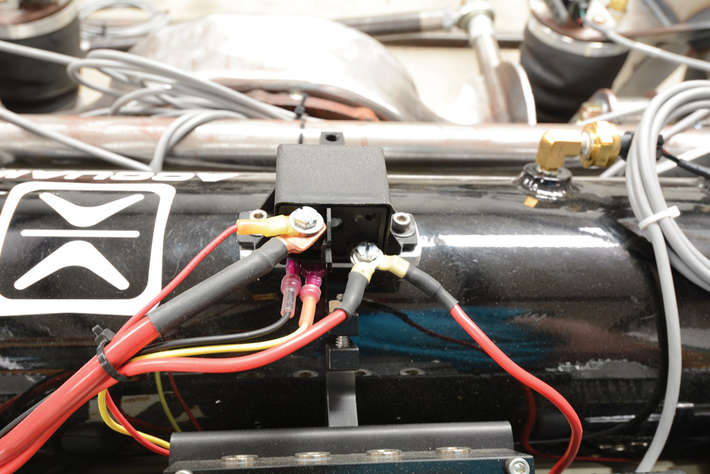
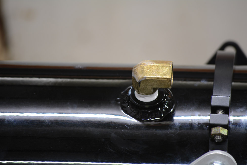
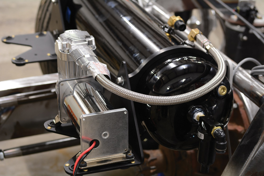
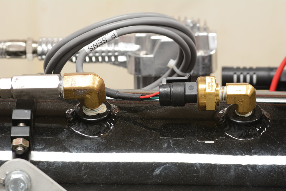
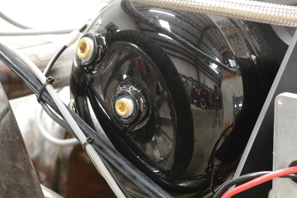
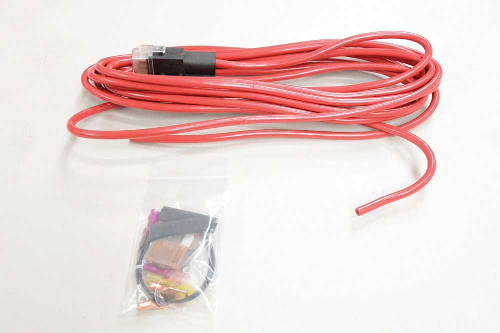
Our two boxes of products came with all of the supplies we needed to install the system. AccuAir provides both written and illustrated directions for an installation process that’s easy to understand. For example, AccuAir’s EXO Mount directions alone give a detailed 11-page description covering everything needed to mount the tank, the compressors with mounts and the VU4 (AccuAir’s solenoid valve unit).

Once we were finished installing the system, we took our truck to the Goodguys Lone Star Nationals in Fort Worth, Texas, to demonstrate how easy it was to install the system and show-off the quality of AccuAir’s parts. We received positive feedback from other vendors and spectators. We are extremely happy with this air management system, and we’re sure that anyone who purchases one will be just as satisfied with it as we are.
[divider]SOURCES[/divider]
ACCUAIR
877.247.3696
Accuair.com
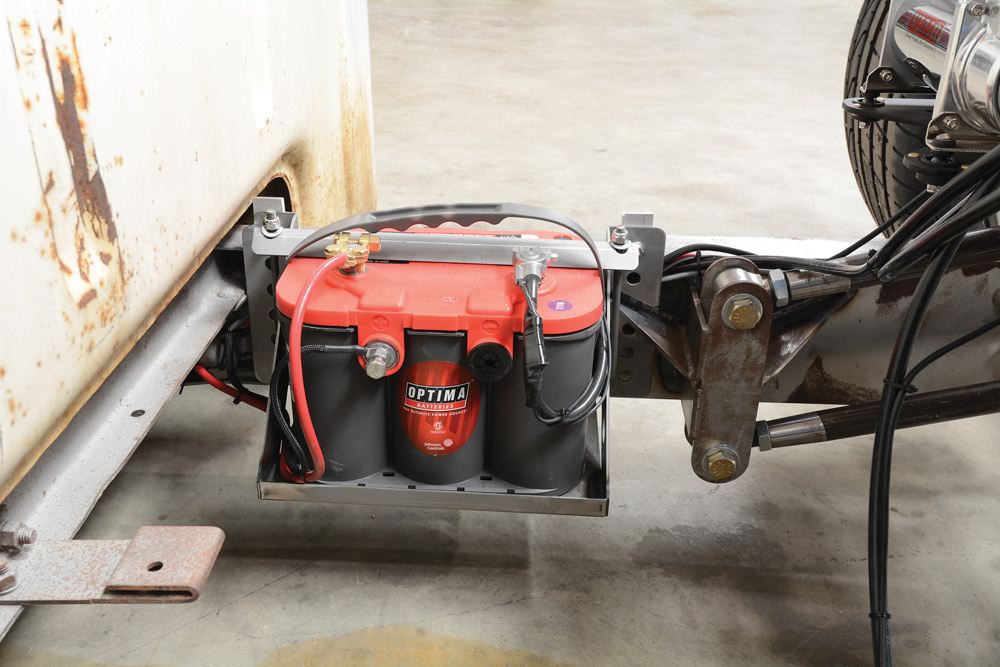
OPTIMA BATTERIES
888.867.8462
Optimabatteries.com
VIAIR
949.585.0011
Viaircorp.com


Department
Aaron Oliver’s Twizted Isuzu P’up Aaron Oliver had a lot to think about when he found himself stranded on the side of the road in… Continue reading
John Mata Jr. . June 01, 2021

Features
Building Much More Than Just a Show Truck There’s nothing more exciting for a young man than his first vehicle especially if it looks anywhere… Continue reading
John Mata Jr. . April 21, 2020

Features
Skatin’ the Streets of New York Buying someone else’s custom ride is always an interesting situation. More often than not, there are some unexpected surprises,… Continue reading
Chris Hamilton . January 22, 2020

Features
Can’t Stop, Won’t Stop THINGS DON’T ALWAYS GO AS PLANNED, ESPECIALLY IN THE CUSTOM TRUCK WORLD. Mike Cannella, a longtime custom truck enthusiast and loyal… Continue reading
Mike Alexander . May 12, 2022
Department
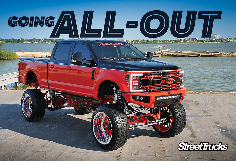
Chance struggled to make ends meet and was finally able to reap the benefits of his hard work and labor. He had a 2011 Ford… Continue reading
phil Gordan . July 28, 2021
Blood Sweat and Gears
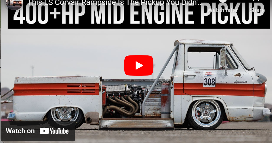
One of the few Corvairs of Canada! This 1962 LS Chevy Corvair rampside has its original patina intact, a 6.2 LS3 engine and a Corvette… Continue reading
STREET TRUCKS STAFF . December 29, 2022


Share Link