Installing a Chris Alston’s Chassisworks rear section | 1967-72 Chevy C-10
JEREMY RICE . January 21, 2020 . C10 Builders Guide
Share Link
Save ArticleLogin to save it
BUILT NOT BOUGHT | INSTALLING A CHRIS ALSTON’S CHASSISWORKS CHASSIS SECTION ON A 1967-72 CHEVY C-10
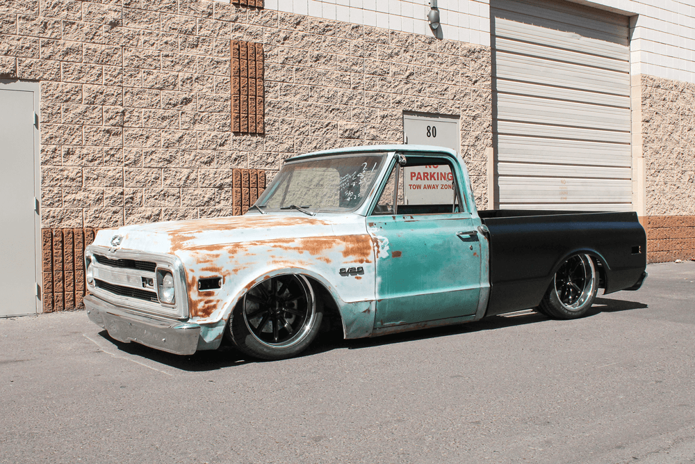
AS MOST OF our readers already know, 1967-72 Chevy C-10s are becoming harder and harder to find. The nice ones are going for large sums even though you often don’t really know what you’re buying. So many issues can be disguised by pretty paint jobs that it can be stressful to find the right truck.
So, what do you do? Do you take your chances and pay big bucks for what looks like a nice truck, or do you look for a project to build or have built? Some enthusiasts really enjoy the build process, even if they aren’t the ones doing the actual work. If the build is put into the hands of a trusted shop, the truck owner still gets to watch his project take shape, and there’s a lot to be said for the enjoyment that goes along with that scenario.
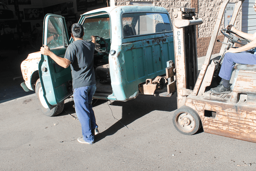
Let’s say you’ve decided to take on a project and you’ve located a truck that no one else would even think of buying. The entire bed is missing; even the rear frame section is missing. There’s no interior, no drivetrain, and remember, there’s not even a rear axle. Now you’ve put yourself in our shoes; this is exactly the type of project truck we’ve located: a truck no one else would consider buying. But, we’ve been in the game for a while and know that we can handle a project like this.
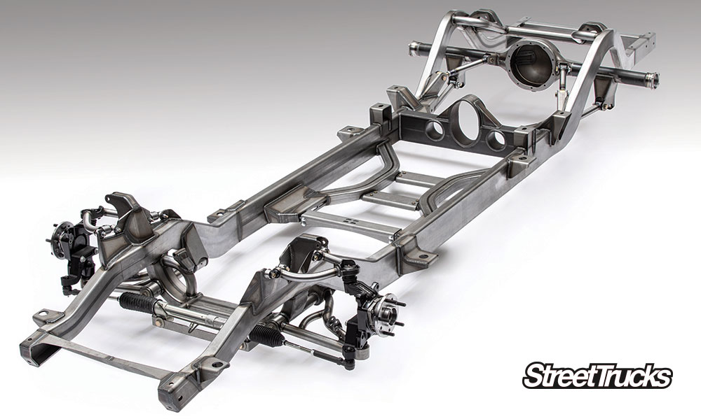
The first thing we need to tackle is the missing back half of the truck. We searched online and discovered Chris Alston’s Chassisworks (CAC), where we found exactly what we were looking for: a complete back-half kit with a sufficient frame rail section so that we could weld it onto what was left of our frame for a complete rolling chassis. CAC has been around for more than four decades, and with more than 7,500 products, it’s safe to say the folks there know what they’re doing. The company’s product line is extensive enough that they offer several options for 1963-72 C-10s.
We knew we wanted the truck to sit low to the ground, but we also wanted to be able to raise it up for driveability. After reading up on the kits listed on the website, we chose the 4-link through bed rear frame clip (P/N KPC RT4LA-C31). Since it’s an airride kit, we ordered the VariShock double adjustable air springs (P/N VAS 132K2-515). We also opted for the Watts-link kit (P/N KPC WLFT-C31-12) to keep the axle centered between the new frame rails.
We placed our order, waited patiently for the parts to show up and got right to work. Check out the process as we turn this frame into a full roller in a single day.
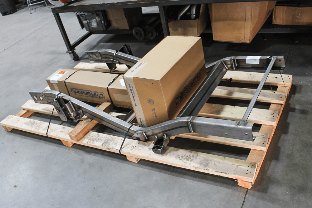
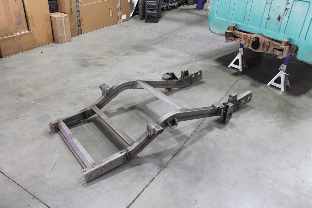
There wasn’t much left of this poor truck when we grabbed it from a backyard for less than $500. We had to get creative in order to get the truck onto the trailer, but once we had it at the shop, the forklift made quick work of unloading it.All of the parts we needed from CAC showed up on a single pallet shortly after we placed our order.We began by unpacking the individual parts, starting with the frame rails. We set them by the truck while we came up with a game plan to get the stock frame married to the new rear frame section.
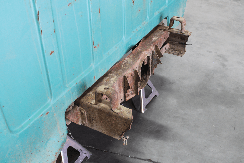
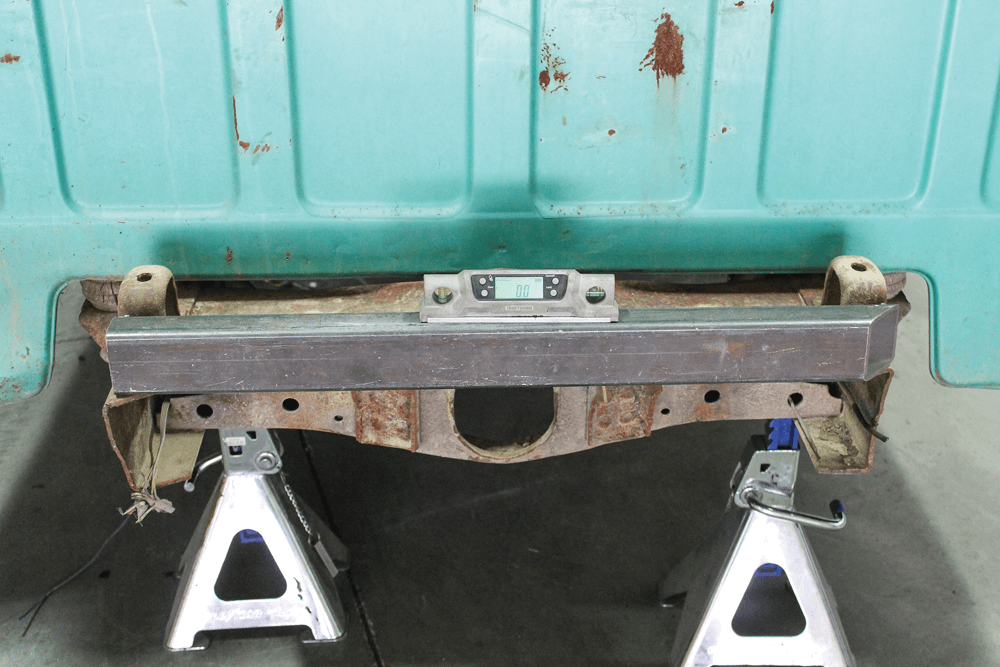
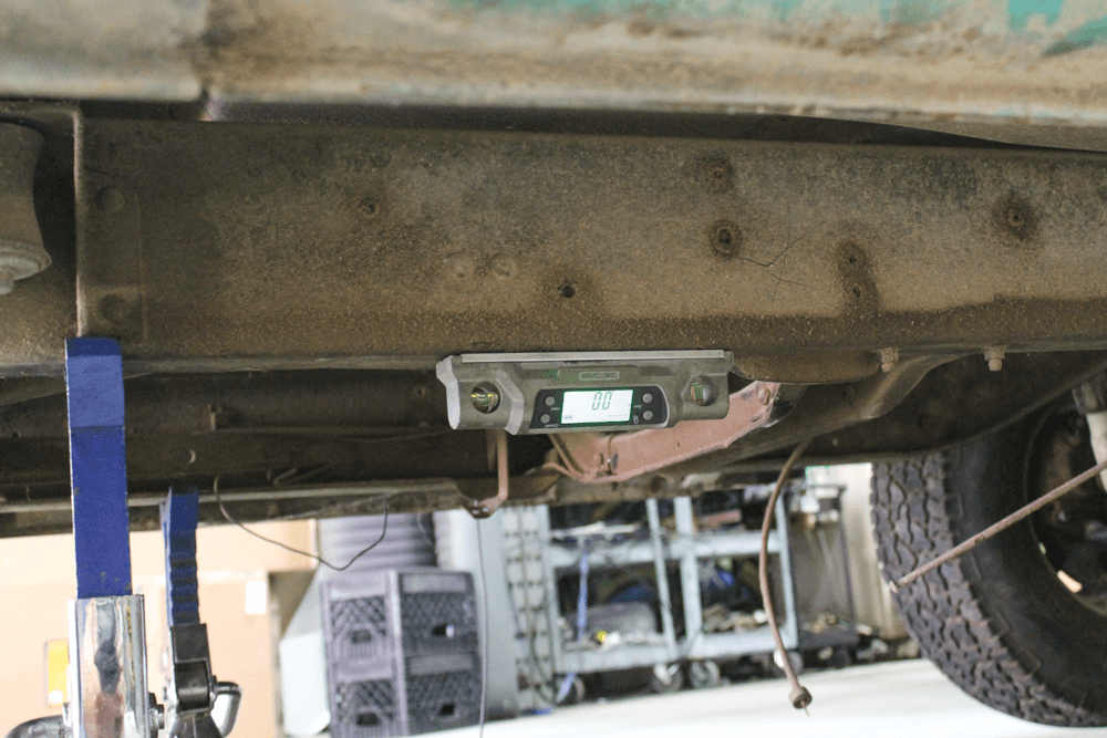
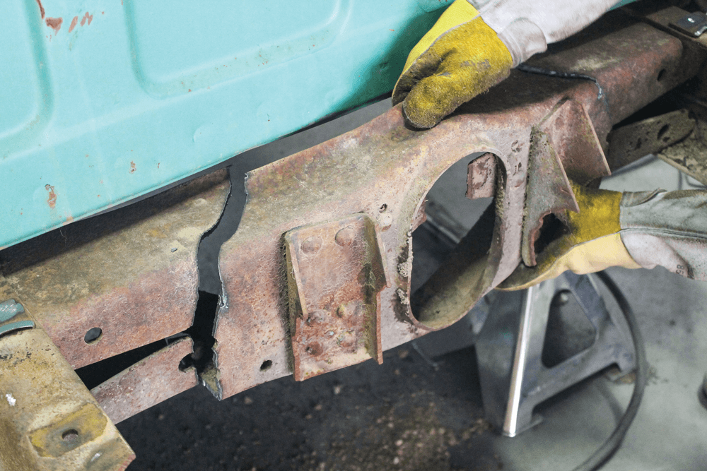
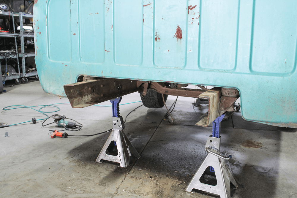
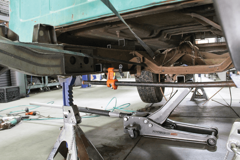
04 We placed the stock chassis on jack stands and leveled it in both directions: left to right and front to back.A couple of things on the stock chassis were in our way and needed to be removed. The forwardmost bed mount will be replaced by the one on the new frame rail, so we removed it first.
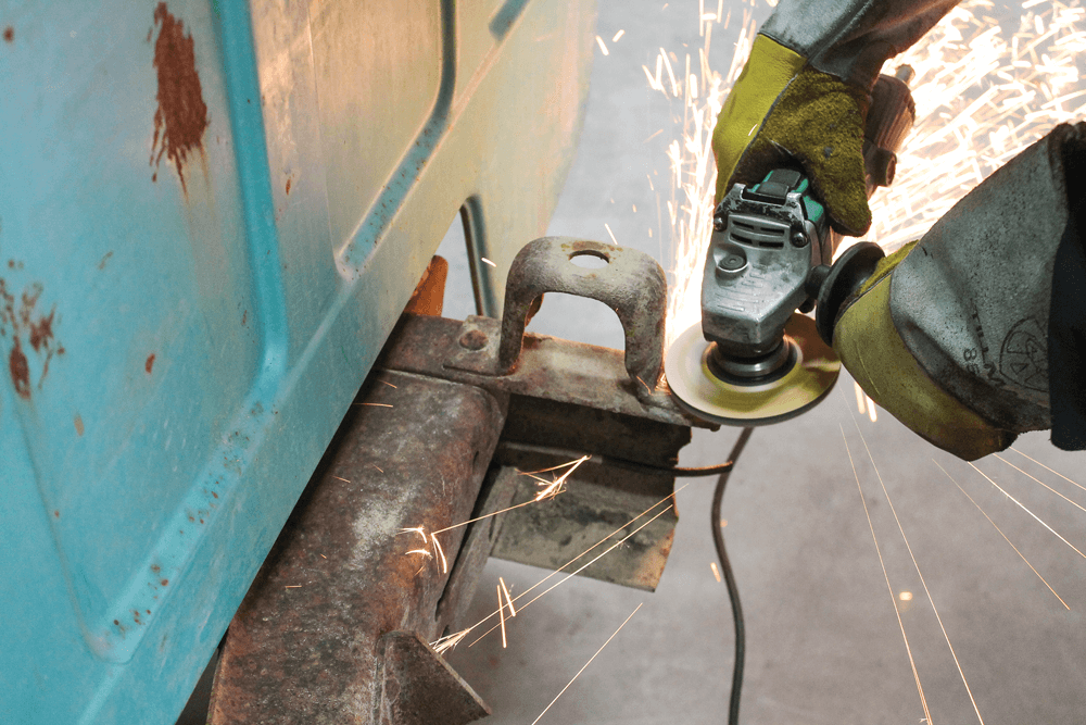
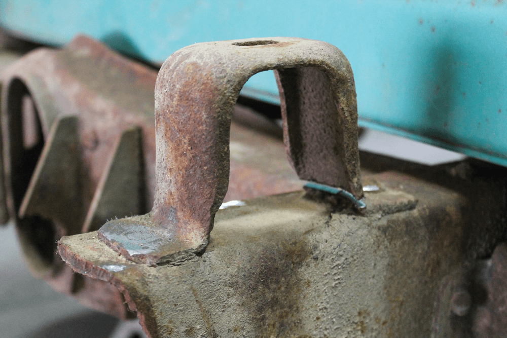
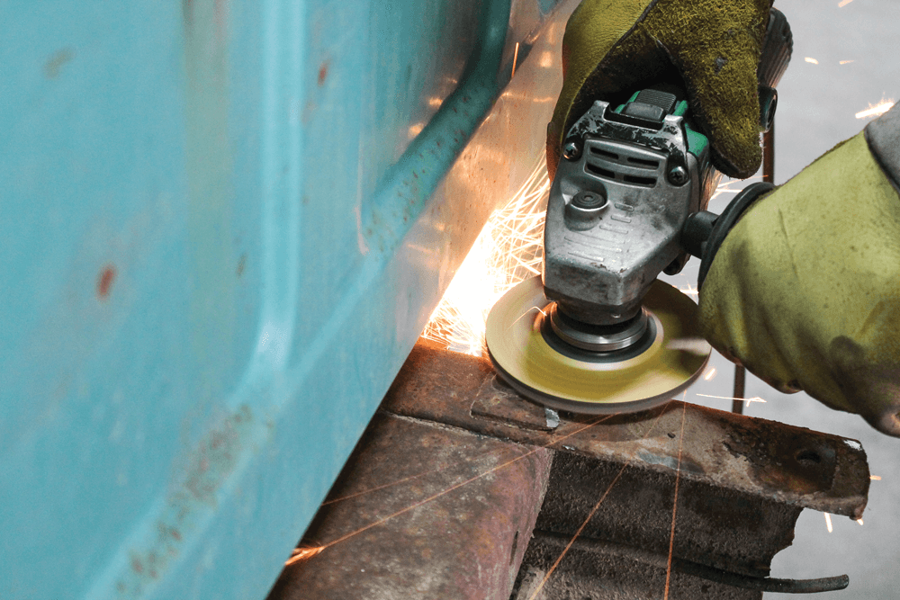
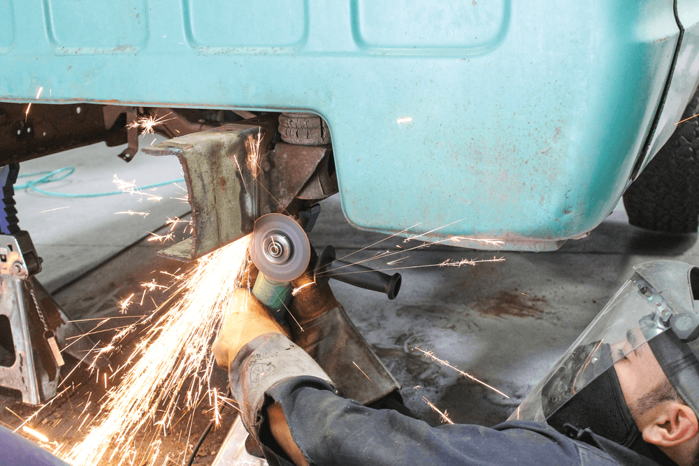
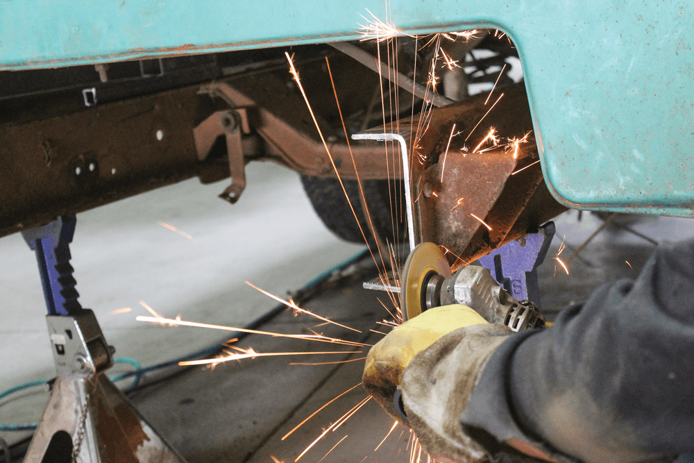
The rivet heads were sanded off using a 36-grit flap wheel. Since we weren’t removing the cab for this job, we cut the front part of the mount with a die grinder for easier access to the front rivet.The sander made quick work of the rivet head. A punch tool and hammer made equally quick work of removing the rest of the rivet.Since the new rear suspension doesn’t rely on the factory trailing arms, the stock cross member that normally houses them also needed to be removed. We made it easier on ourselves by cutting a big chunk out of the middle of the cross member before attacking the attachment points at the frame.Using the same tactics with the flap wheel and the punch, we removed all of the rivets that held the trailing arm cross member in place. It was actually a good thing we didn’t start out with a full frame. Someone had already done a bunch of hard work for us by removing all of the other pieces of the rear frame.
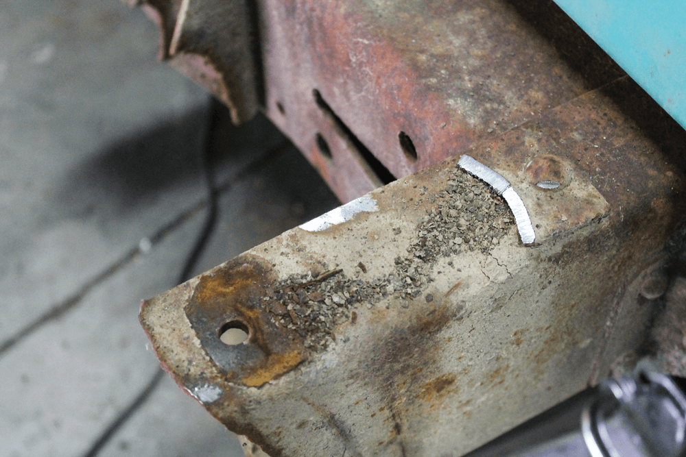
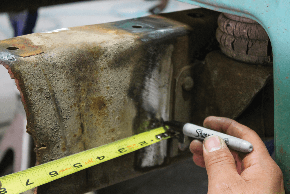
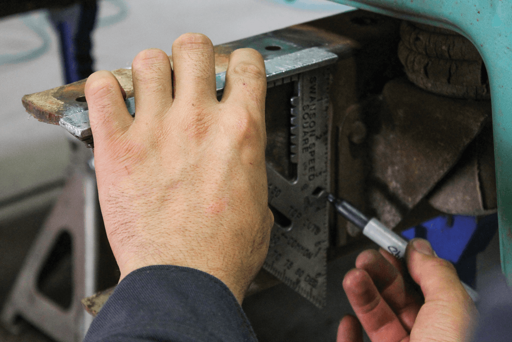
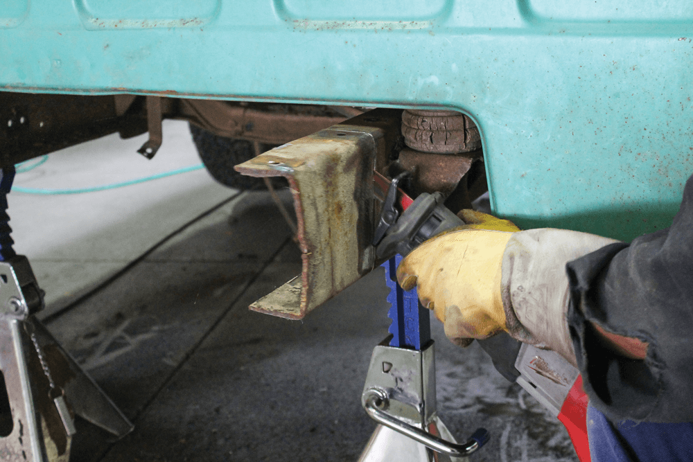
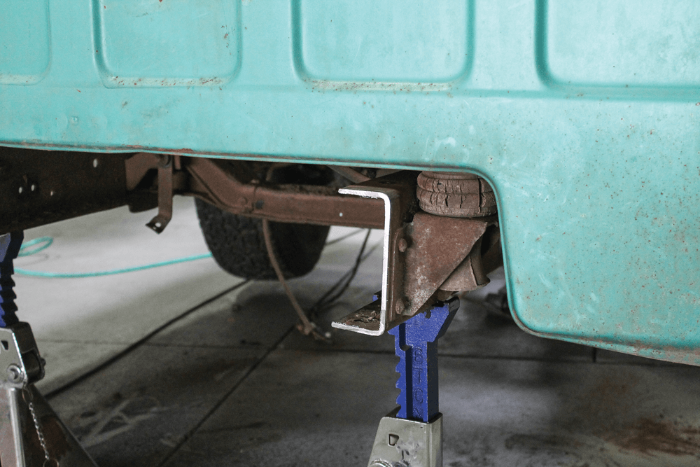
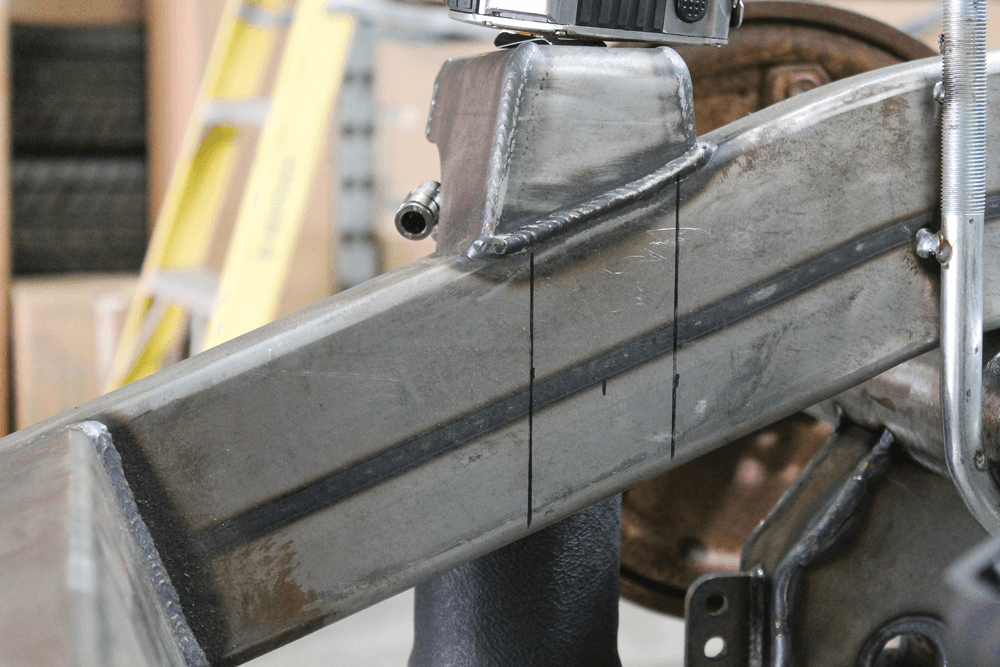
Closely following the instructions included with the kit, we measured 3/8 inch behind the rear cab mount flange and made a mark. Then we used a square to draw a line from that mark at the top of the frame to the bottom. We cut here.11 A combination of a sawzall and a cut-off wheel was used to make a perfectly straight cut down the frame rail.
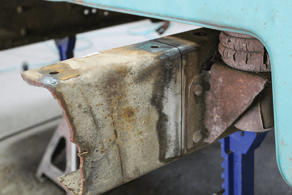
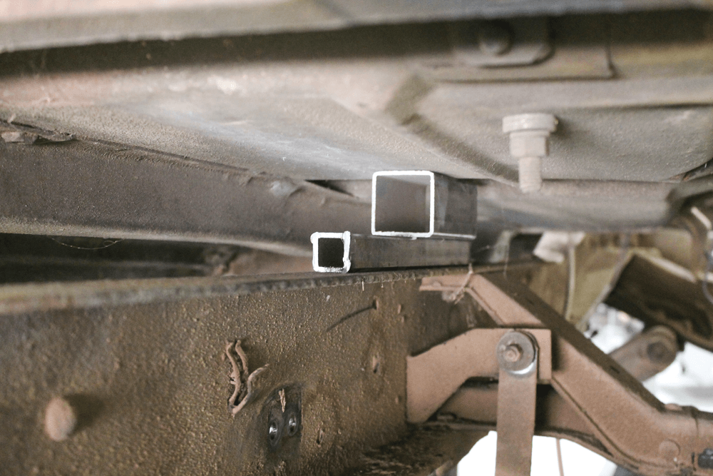
This is how the frame rail should look after the cut. Since we really only had to remove a few inches of frame rail, it was fairly easy to do. If the stock frame rails had been hanging off the back, it would have been necessary to support them with additional jacks stands.Since the rear cab mounts needed to be removed in order for the new back-half to slide into the stock frame C-section, we unbolted the cab from the frame and spaced the cab away from it with scrap square tubing. This is just to hold the cab in place while we remove the mount.
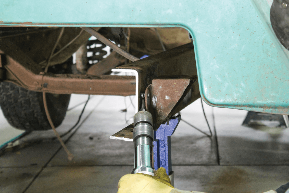
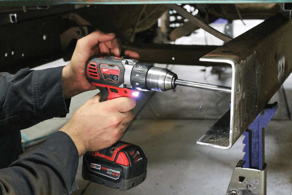
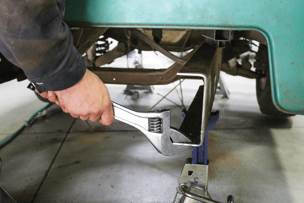
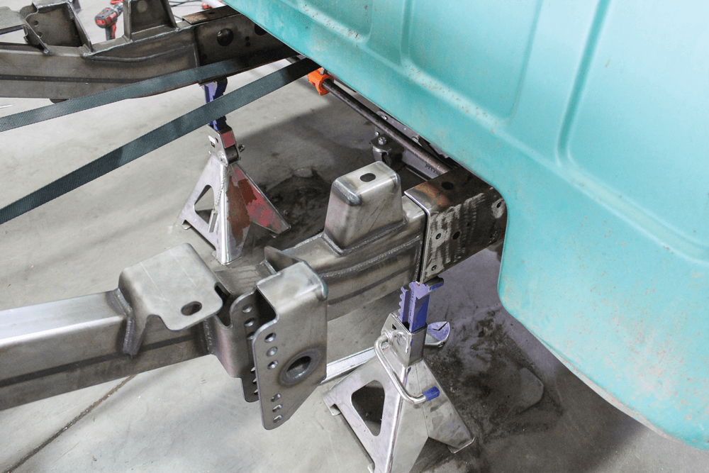
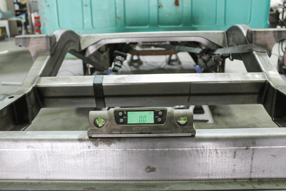
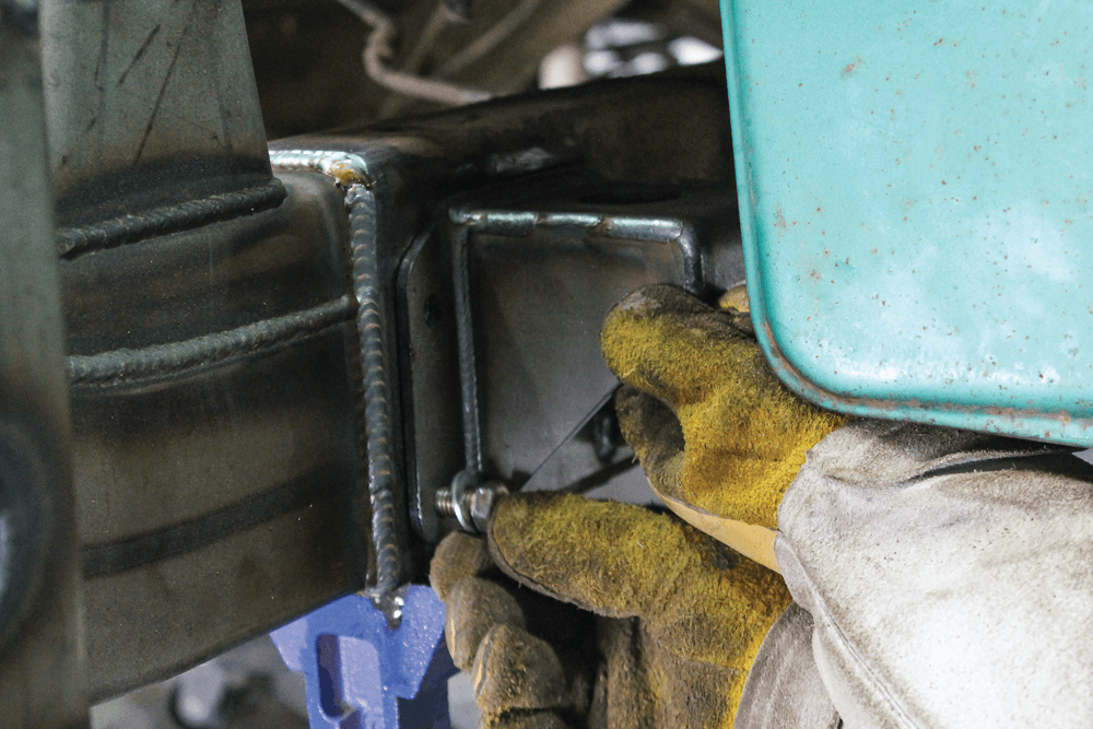
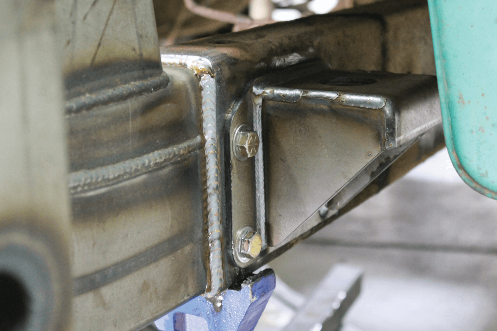
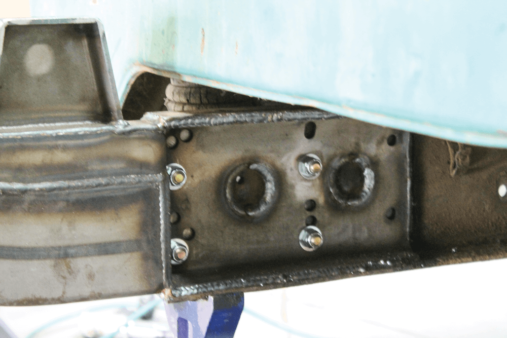
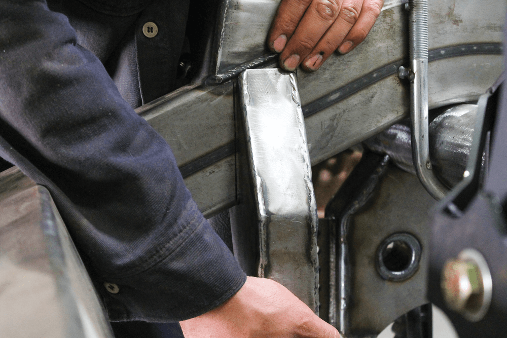
Using the same method we used earlier, we sanded down the heads of the rivets to free the mount. However, these were a bit more stubborn, so we had to break out the pneumatic air hammer to remove a few of them.The holes for the cab mounts were drilled using a 7/16-inch bit. These holes will eventually help us align the new rear frame section.After taking some quick measurements and referring to the provided instructions, we used a large crescent wrench to flare the top and bottom edges of the frame to make slipping in the new section easier.With jack stands in place, the new rear frame section was positioned and partially installed.We were able to get it pretty far into the stock frame, but it’s a tight fit, which it should be.Using spreader clamps, we got creative and spaced the frame just enough to slide it in the rest of the way.Using ratcheting straps and a few taps with the hammer, we were able to get the new frame section perfectly level with the rest of the chassis.Since the holes we previously drilled for the rear cab mount to line up with the holes in the new frame section, the new rear cab mounts bolt right up. These bolts sandwich the cab mount, stock frame and new frame.After triple checking that everything was level and square, the new frame section was welded to the stock frame. We started this process with the outside vertical line where we cut off the rear part of the stock frame rail.With this part welded, we could drop the cab back down on the new mount.We turned our attention to the inside of the frame. This is where most of the kit’s strength comes from. We welded around the entire edge of the connection and the two plug weld holes. You can also see the four nuts and bolts that lined everything up with the rear cab mounts.
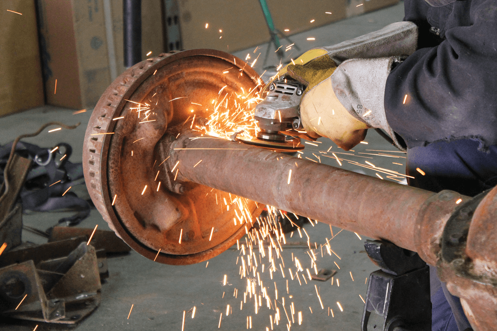
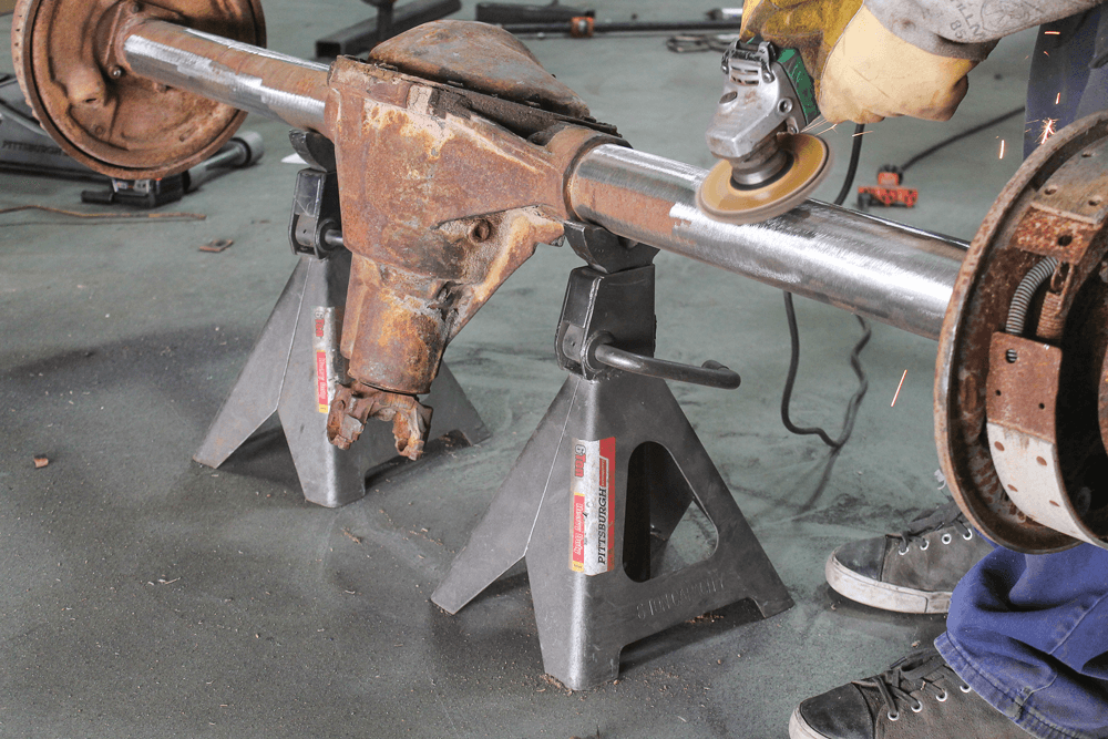
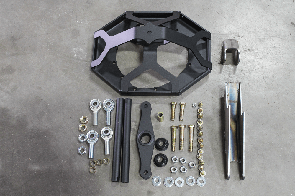
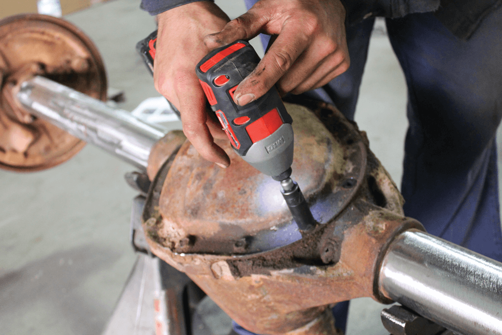
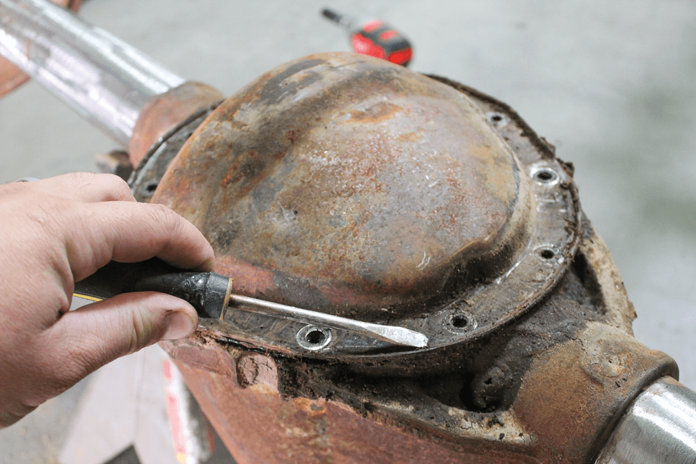
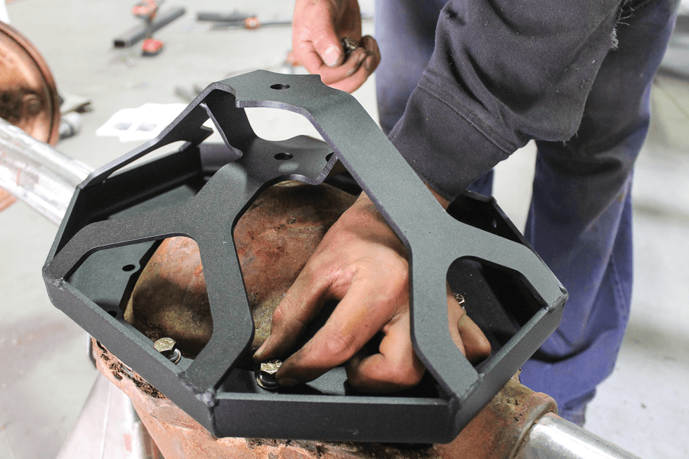
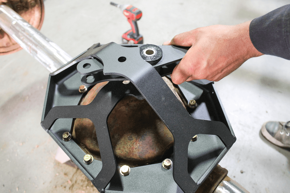
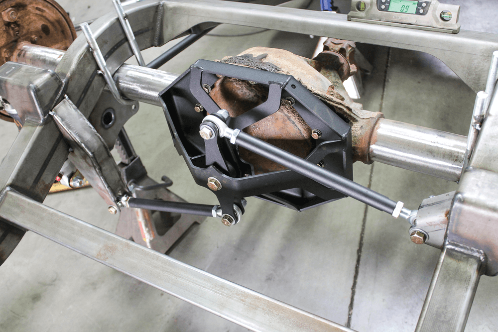
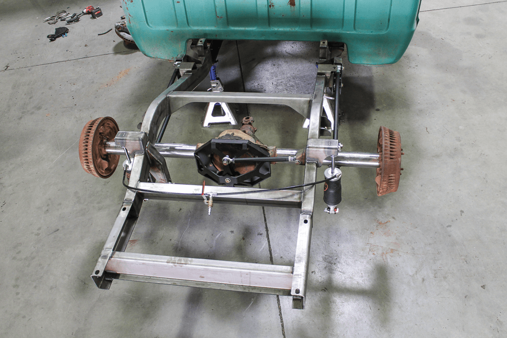
Now that we have the new frame section from CAC permanently in place, we can turn our attention to the suspension aspect of the kit. We picked up a used GM truck 12-bolt axle from the local parts yard and started cleaning up the axle and removing all of the old bracketry.Here’s everything that came with the Watts-link upgrade for the rear frame package. A Watts-link is considered an upgrade from the standard pan-hard bar because it will keep the axle centered throughout travel. On a coil-over suspension, the pan-hard bar would be perfectly fine because the suspension isn’t traveling as much; however, since we will be using air springs, we wanted to do the upgrade and keep the axle centered.Installing the brace for the center pivot of the Watts-link required the removal of the differential cover hardware.Since this axle was laying around in the parts yard, and probably has well over 100,000 miles on it, we needed to clean up the sludge that had built up around the edges of the diff cover so that the new bracket would sit as flat as possible.With the axle prepped, we installed the new Watts-link pivot bracket using the provided hardware.
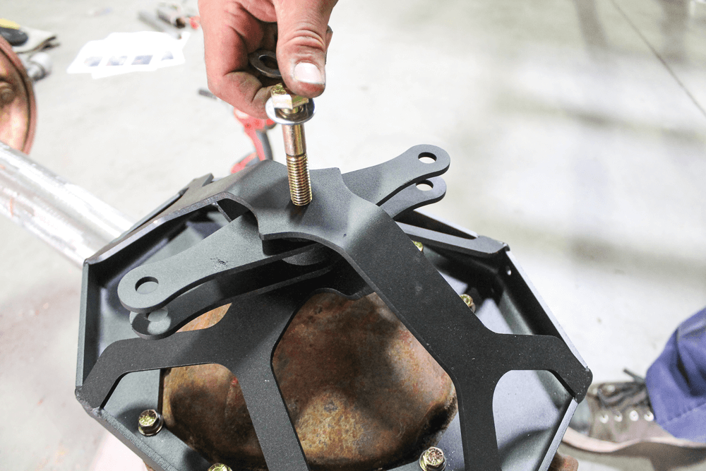
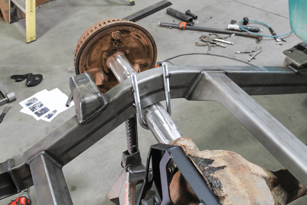
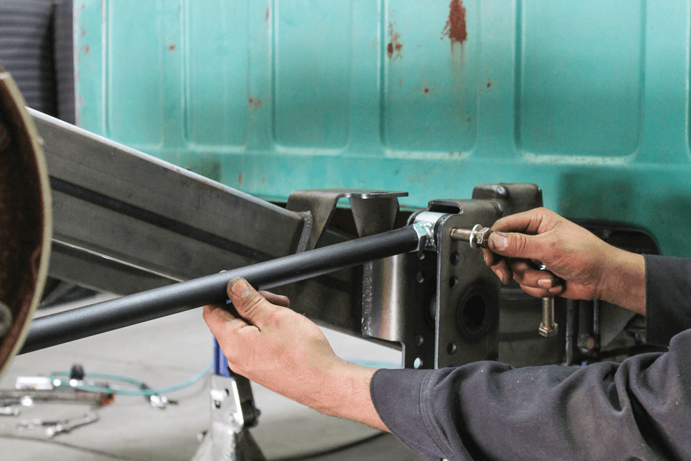
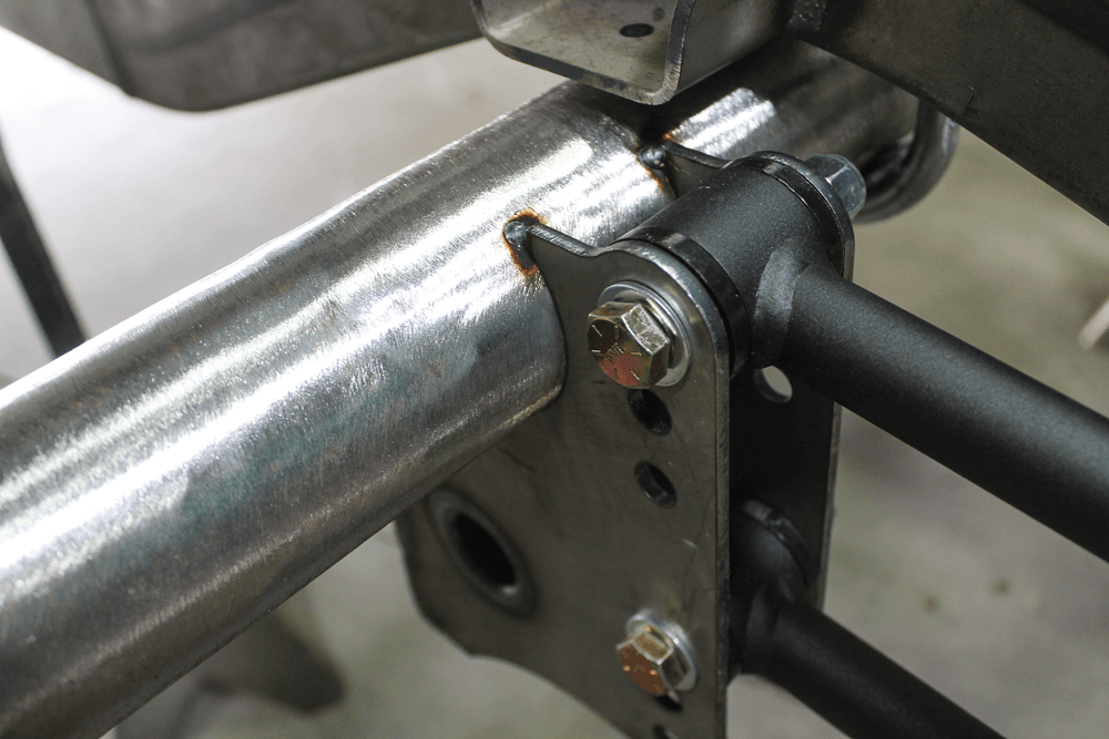
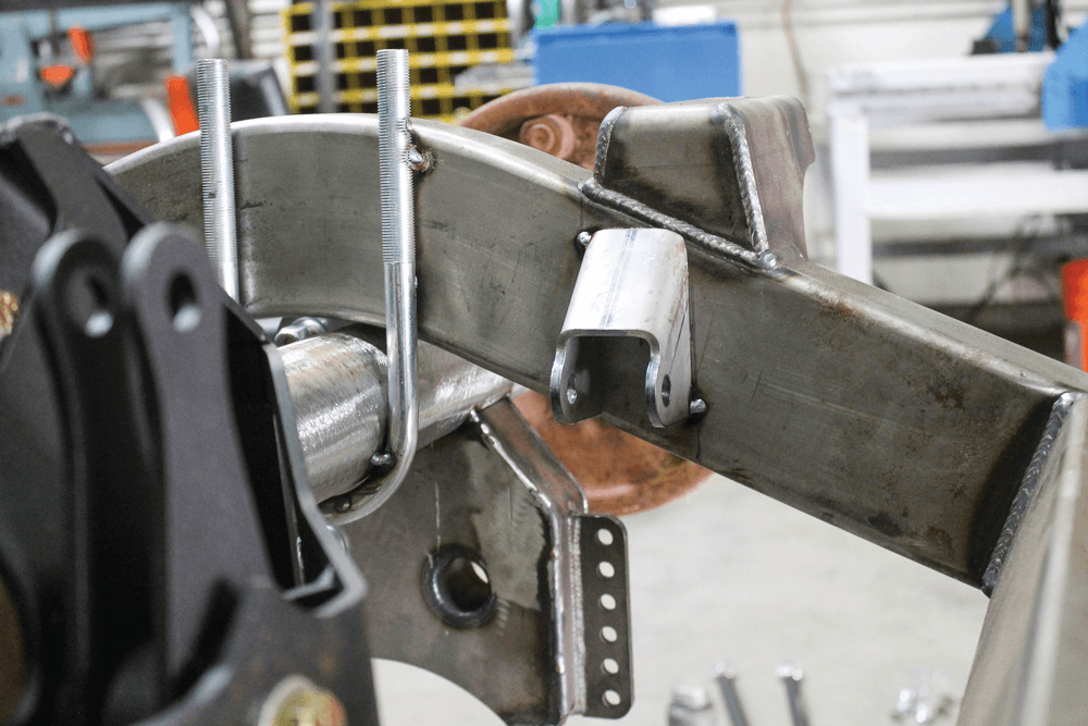
The actual pivot was slid in between the mounting surfaces and bolted in with the new hardware.Using the bump stop mounts on the outside surfaces of the frame, we centered the axle and used some old U-bolts to temporarily hold it in place so that we could set up the 4-link suspension.Speaking of the suspension, here are all of the actual suspension components that came as part of the rear frame kit.After assembling the four identical link bars, we began installing them into the mounts already attached to the new frame.Since we had the axle temporarily secured in place, we were able to hold the 4-link mount against the axle and position the first link bar.
We repeated the process with the lower link, keeping the link bars parallel by using the highest hole for each mount.
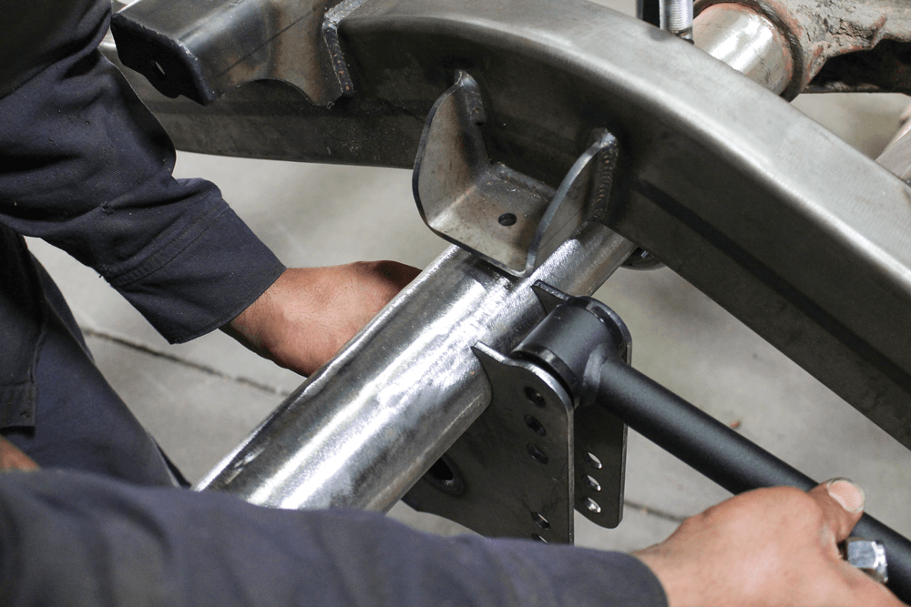
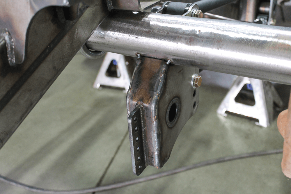
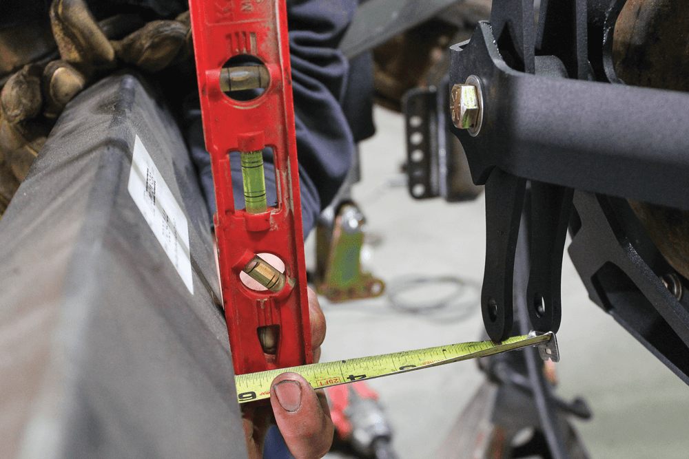
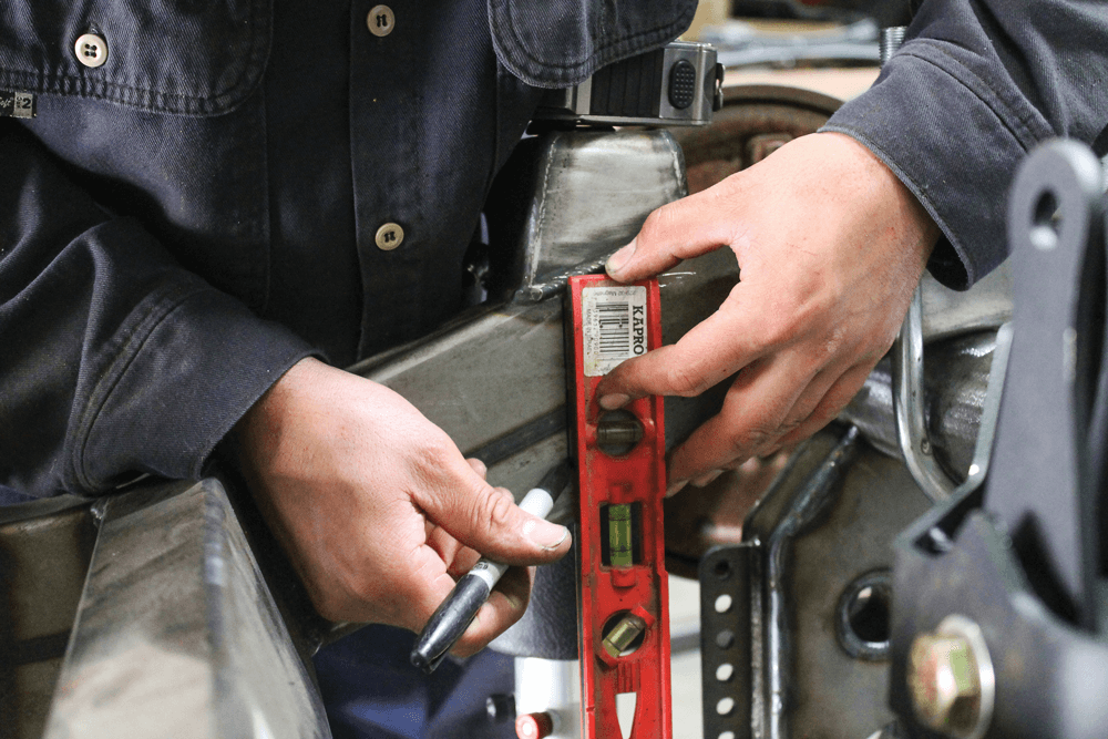
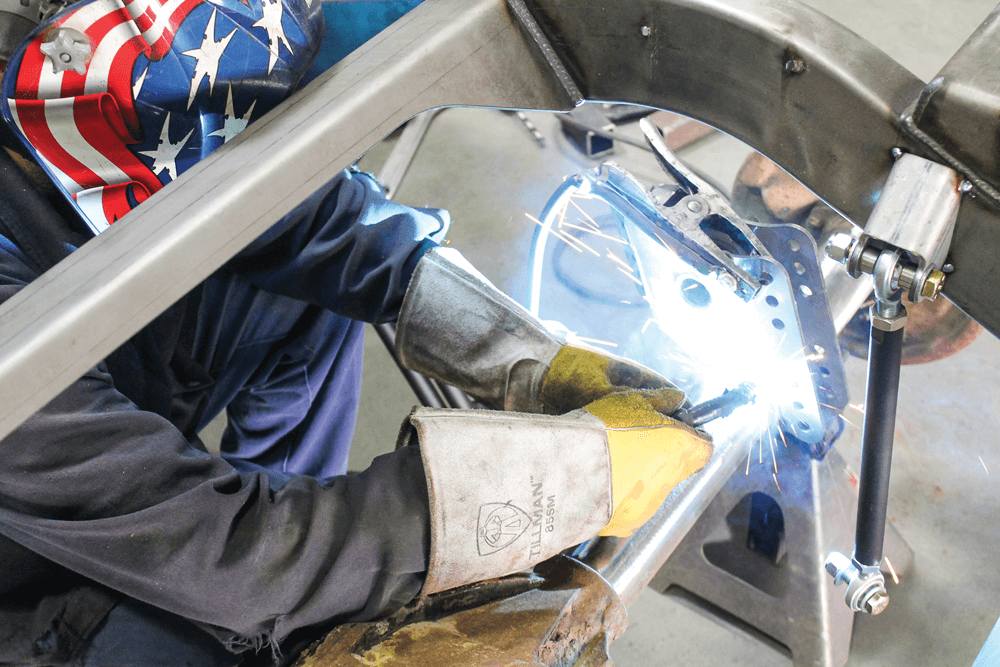
The position of the link mount on the axle was checked to make sure it was sitting in the correct location. After triple checking our measurements, we tack welded the mount in place and repeated the process on the other side.A lot of measuring was necessary throughout the process, and it was very important to make sure everything was where it needed to be so the truck drives straight down the road and handles correctly. Since the Watts-link is an upgrade, the frame mounts do not come installed on the frame rails, which meant we needed to figure out where to place them. Using the axlemounted pivot, we measured the distance between it and the cross member located directly behind the axle.Using a level and a tape measure, we transferred the center of the Watts-link pivot to the driver’s side frame rail.
With the centerline marked, we measured out half the width of the mount each way and marked the location of the Watts-link frame pivot.The mount included with the kit was sized and notched perfectly so that it sat correctly against the side and bottom of the frame rail. Once we had the mount aligned, we tack-welded it in place.Using the same method, we also located the passenger’s side mount on the other frame rail. We tack-welded the mount in place temporarily because wanted to make sure everything cycled correctly before burning it in for good.
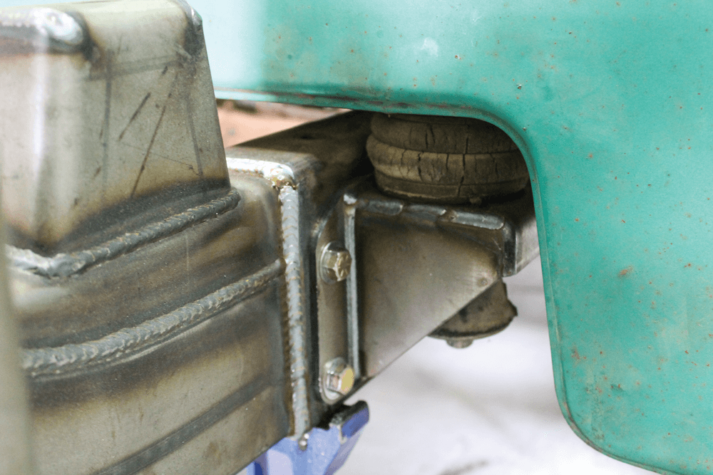
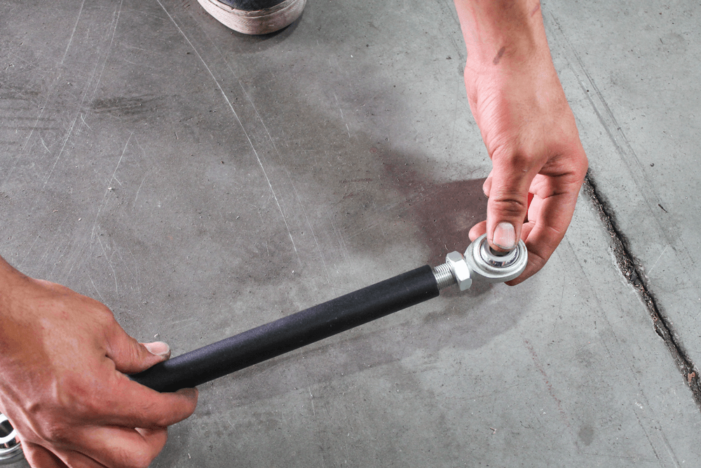
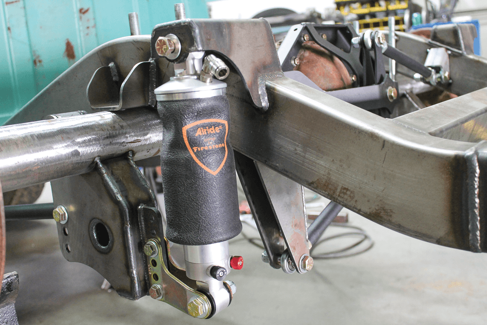
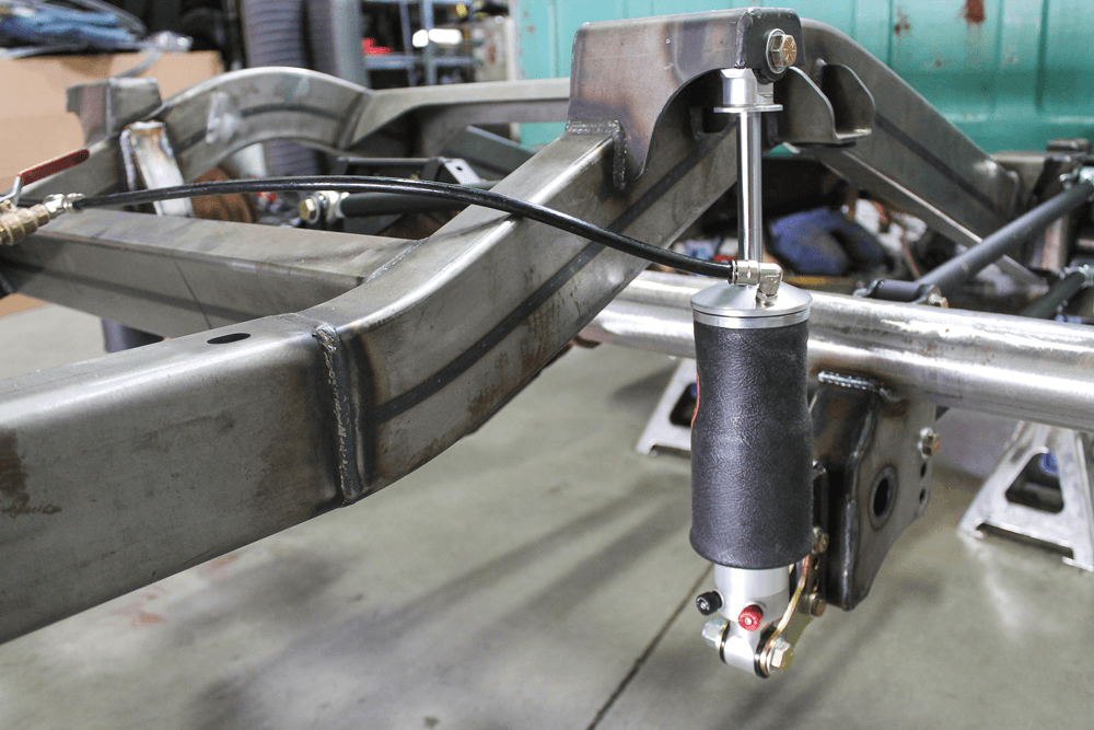
Next, we assembled the two Watts-link pivot bars with the provided heim joints and bolted them in place. Each bar has a left and a right heim, which makes adjusting the Watts-link super easy.The last piece of the suspension puzzle was the air spring. These are the 5-inch Varishock Shockwave double adjustable air springs. Basically, it’s an adjustable sleeve-style air diaphragm over a double adjustable shock that has 16 steps for compression and 16 steps for rebound adjustment. This allowed us to really dial in the suspension’s ride quality.
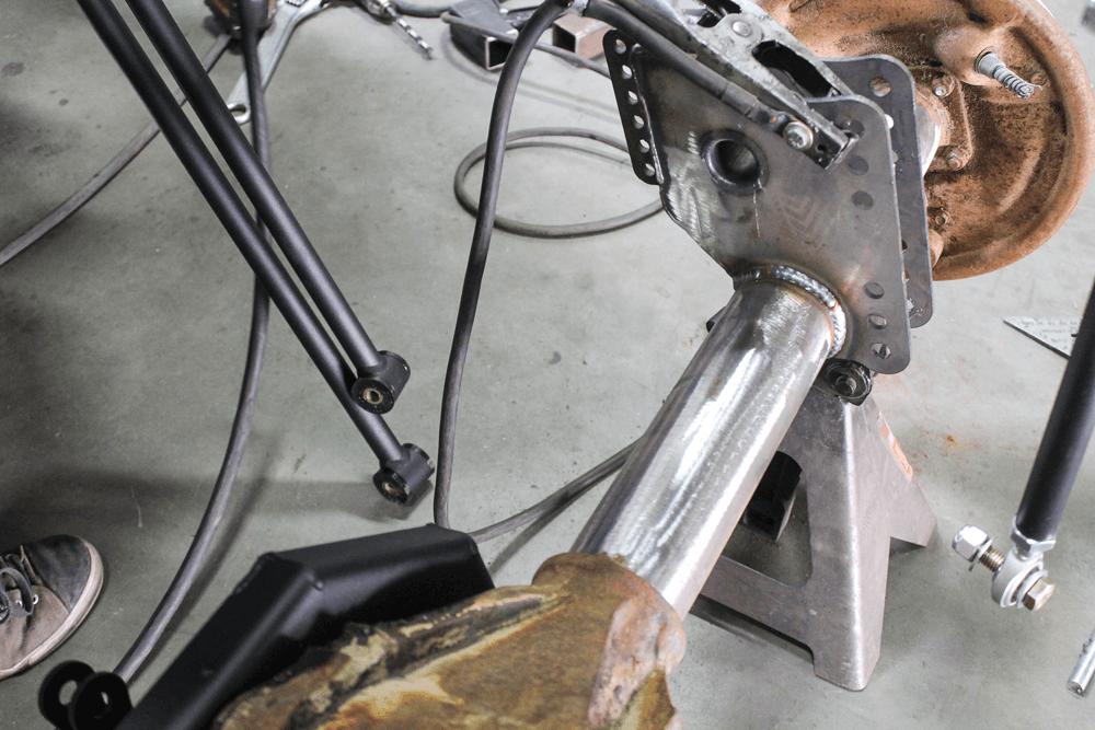
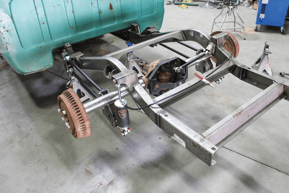
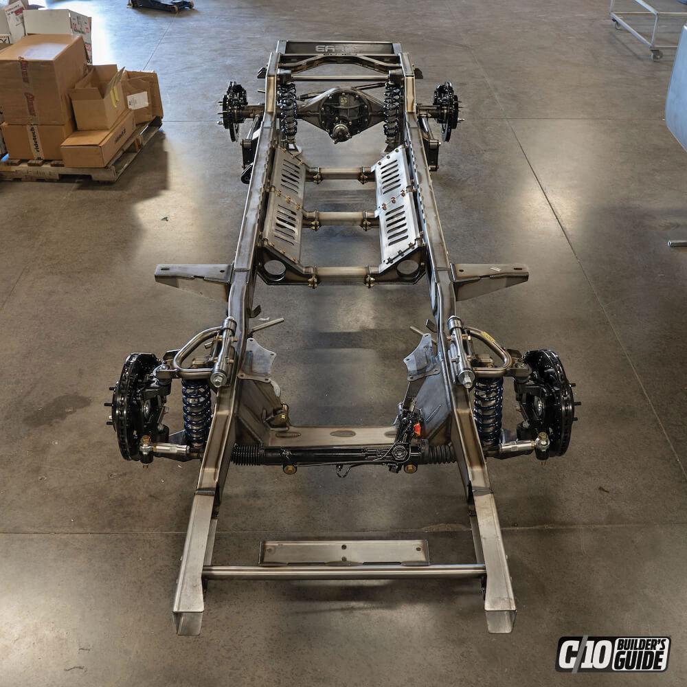
After temporarily installing all of the suspension components and cycling the suspension travel, we tore the whole thing apart to finish-weld all of the mounts on the axle and frame rails.Once the welds had cooled off, we reinstalled everything and hooked up some temporary air lines to lift and lower the truck.
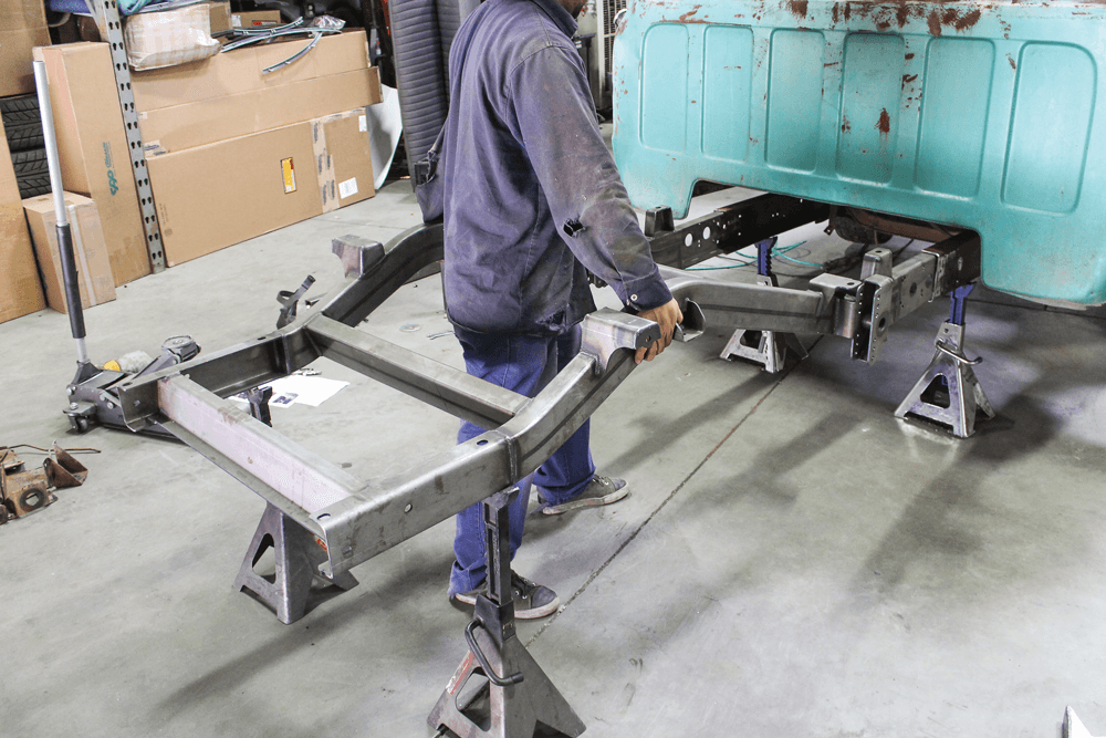
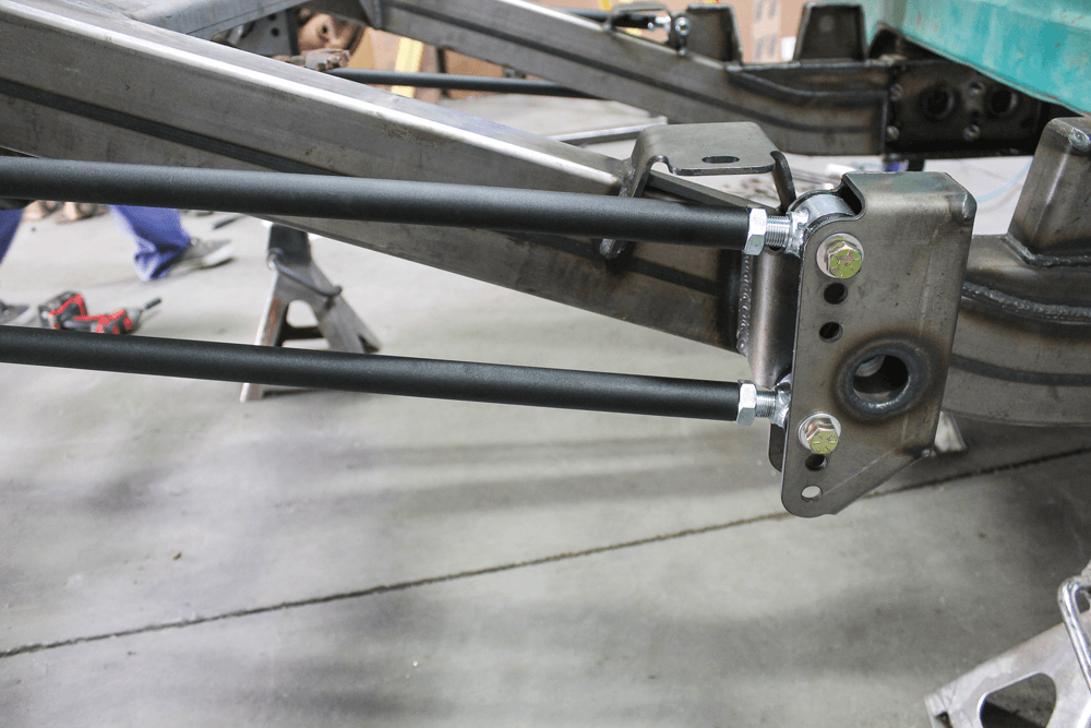
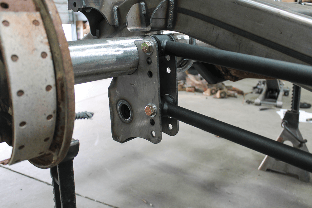
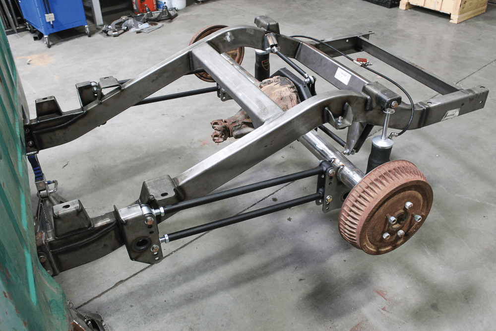
Here are a few different angles of the new rear frame section from CAC. One thing we haven’t mentioned yet is that this whole kit fits a short-bed or a long-bed truck, so it would also be a great way to transform a long-bed into a short-bed.
Of course, we weren’t just going to do the rear frame. This truck and its rebuild will be the focus of upcoming tech articles. Make sure to check back as we continue to bring this truck to life.
We use cookies to enhance your browsing experience, serve personalized ads or content, and analyze our traffic. By clicking "Accept All", you consent to our use of cookies. Visit our Cookie Policy for more info.
 JEREMY RICE
.
January 21, 2020
.
C10 Builders Guide
JEREMY RICE
.
January 21, 2020
.
C10 Builders Guide


Share Link