streettrucks . November 11, 2020 . C10 Builders Guide.
Share Link
Save ArticleLogin to save it
So, you bought an old C10 and you just don’t love the stance? Let me guess—you want it “hammered on the ground, but still enjoyable to drive.” Confidence and driveability in your air suspension are what you need. If you’re looking to put air ride on a classic ’63-’87 C10 but want to make sure you are satisfied after all the time and money spent to get there, consider this GSI Machine and Fabrication C10 frontend suspension kit.
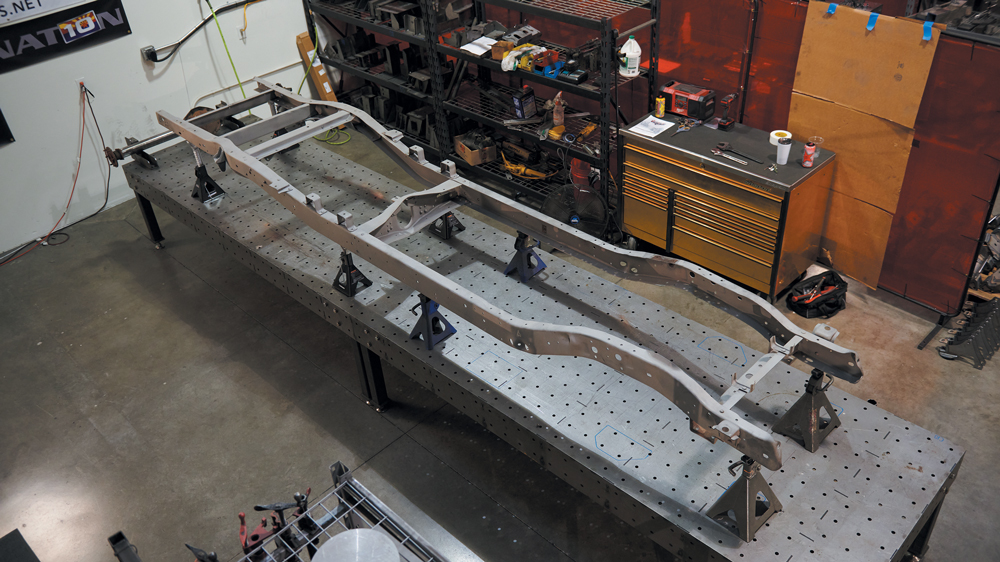
A true bolt-in, bagged suspension system with superior geometry specifically designed for a stock C10 chassis with air bags, this kit accepts large-diameter wheels and tires up to 31 inches tall. This kit narrows the track width, making wheel options greater, and brings the crossmember and lower control arm pivots up out of the way so your frame rails lay flat on the ground when aired out. This system also upgrades the steering to a power rack-and-pinion unit and utilizes disc brake spindles, which are all supplied by GSI when you order the complete kit.
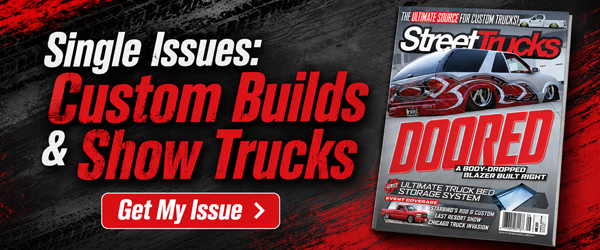
We start with a bare ’64 C10 longbed frame, which is the perfect canvas for our build plan. We will be converting this to a shortbed wheelbase later using a GSI back half. We stripped off all unnecessary suspension components prior to sandblast. With the chassis placed on jack stands, leveled front-to-back and side-to-side, we can begin our install. A frame table isn’t necessary, but a flat surface is. The kit we will be installing fits frames from years ’63-’66 (Part #120-2001) but the company also offers the same kit for ’67-’72 (Part #125-2001A) and ’73-’87 (Part #130-2001A).
In this article we will show you step-by-step how simple it is to achieve all of the above in a few hours’ worth of work.
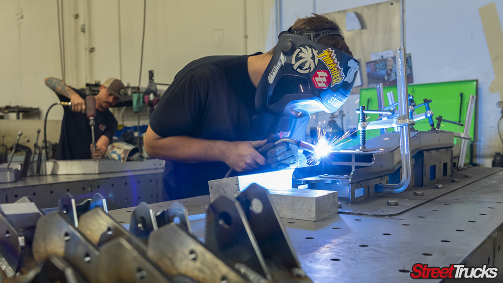
We grabbed a longbed ’64 stock chassis, stripped it down to its bare bones and had it sandblasted by Matador Powder Coating in Mesa, Arizona. When we got the frame back, we brought it to our fab shop and set it on the frame table. This install can be done without the use of specialty tools. You will need a press for the ball joints and bushings, but otherwise a floor jack, sockets, ratchets, wrenches, a couple of jack stands and a drill will get it done.
With all the parts and hardware setup and ready to go, we will follow the supplied instructions and take you through a step-by-step install. Let’s go!!
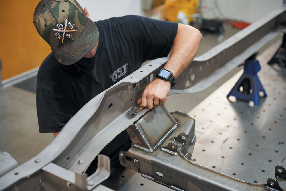
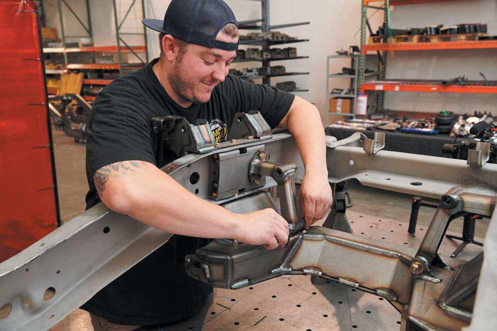
Place the GSI crossmember under the chassis. Using a floor jack, lift it up to meet the frame. Using two of the 1/2-inch bolts, locate the crossmember using factory holes from the original crossmember. Run the center bolts in, but don’t tighten them all the way. Once the assembly goes together loosely, we will go over and tighten everything down to spec.
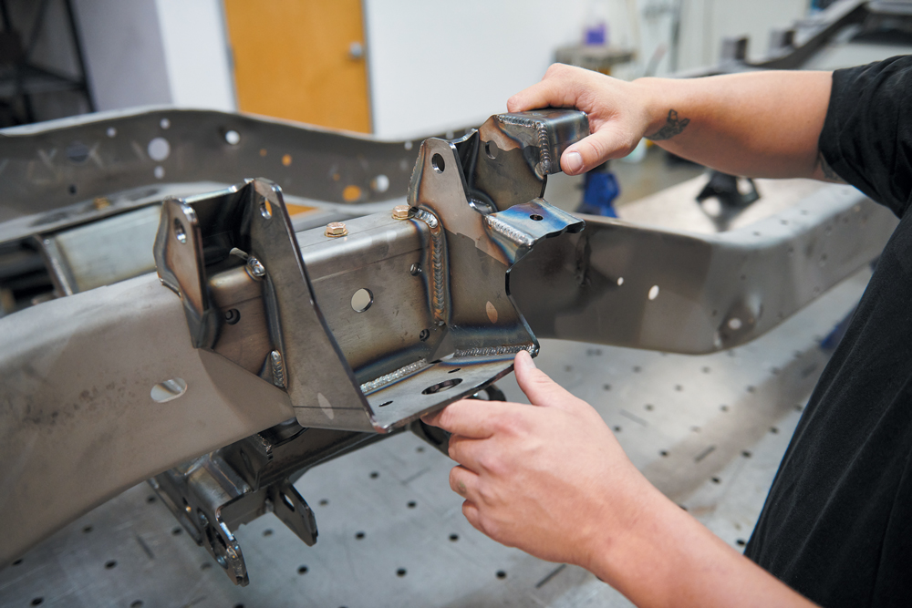
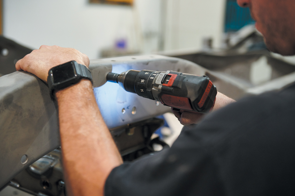
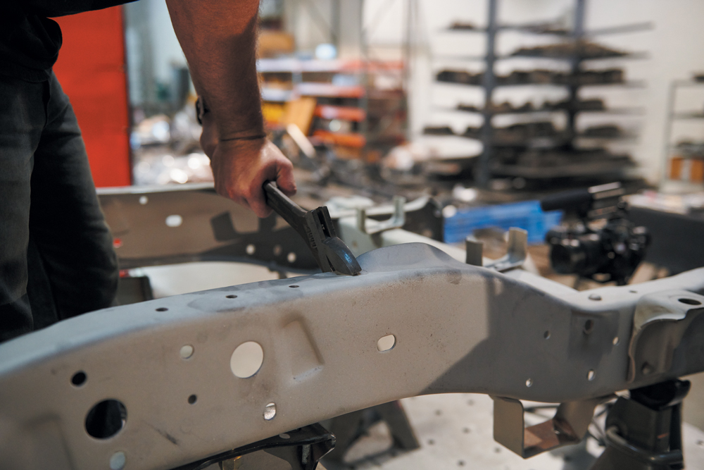
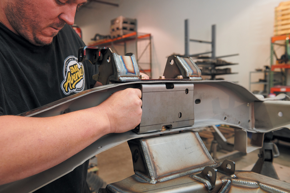
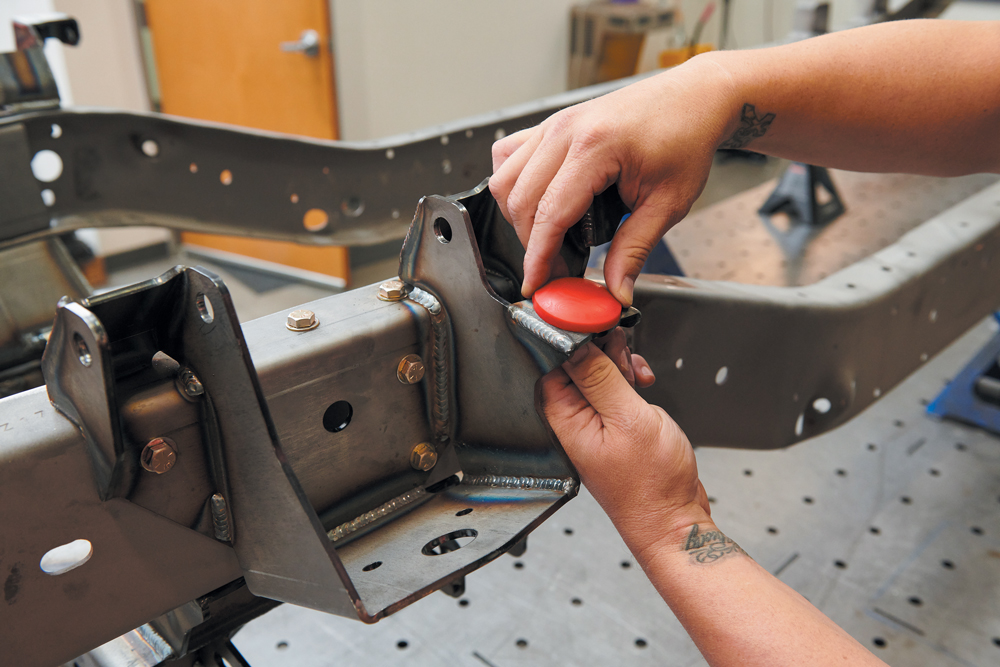
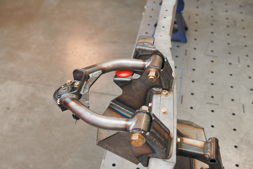
Starting with the driver side, we install the upper hat (which is also the airbag/upper control arm mount) using the top three bolt holes. We need to snug these ones up so we can use the part as a template to mark and drill three more 3/8-inch holes per side. There will be one side hole in the part that matches the frame to ensure proper alignment. Once we mark the hole locations, we will remove the hat and drill the holes out to size.You might find a raised area in your factory frame on the passenger side; this will get in the way of the passenger side upper hat. If your frame does have this, you can pull it down with a crescent wrench or cut it clean and blend it. Only a small portion of it needs to be flattened out. We went with the crescent wrench method. Use the passenger side upper hat as a guide to see how much you need to move. Once the hat sits flat, you have done enough, and you can drill the side holes.Install the inner frame braces inside the frame rails. We use the three bolts from the upper hat to pass through the hat, the frame and the brace, tying all three together. These combined pieces provide motor mount location and add strength between crossmember and chassis. This is a tight area, so have some patience when installing the hardware on the backside. A 9/16-inch ratchet wrench will be our friend during this step.Next we will drop the motor mounts in place and bolt them in. These perches can support a variety of different engine configurations with the use of GSI engine adapters for LS, BB and LT. Once the motor mounts are installed, we can go ahead and tighten everything up. Torque specs per bolt size are included in the instruction manual.GSI has integrated the use of a bump stop to limit the droop at just the right amount of lift, reducing excess ball joint stress while still providing plenty of lift for driving conditions. This feature also protects the suspension if the truck is being worked on while on a two-post lift. The bump stop bolts onto the upper hat in its specified location, one on each side.
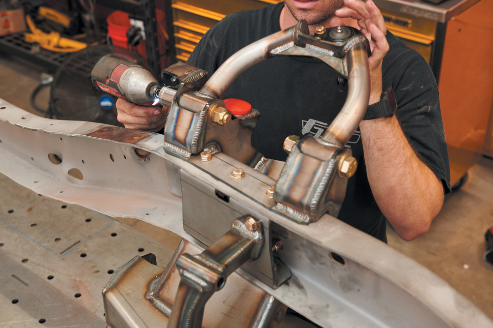
Now we install the upper control arms. With the poly bushings, steel crush sleeves and ball joints assembled, slide the arm into the upper hat. These may take a little persuasion but nothing a rubber mallet can’t handle. The upper control arms are the same and there is no designation from right to left.
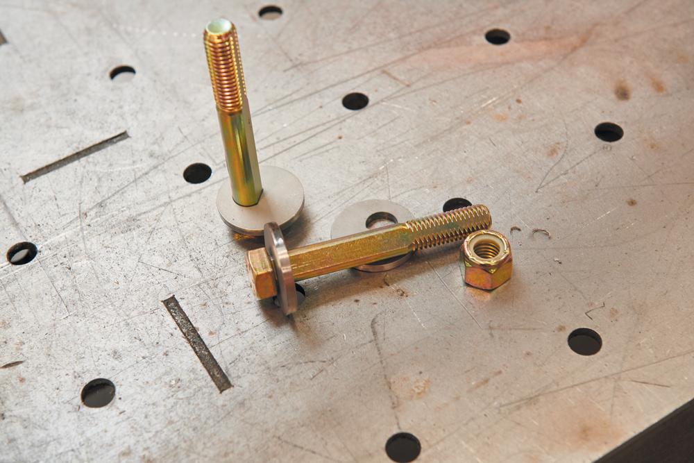
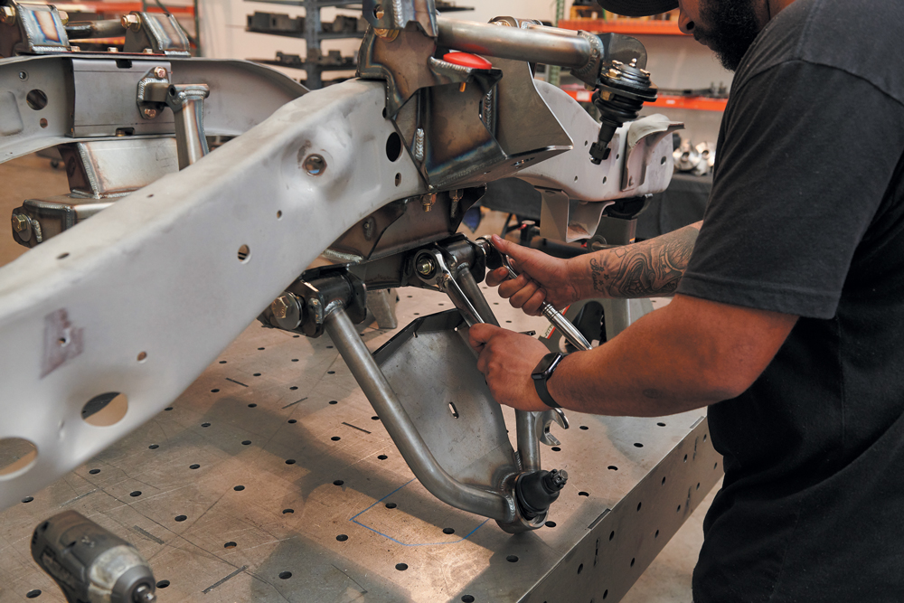
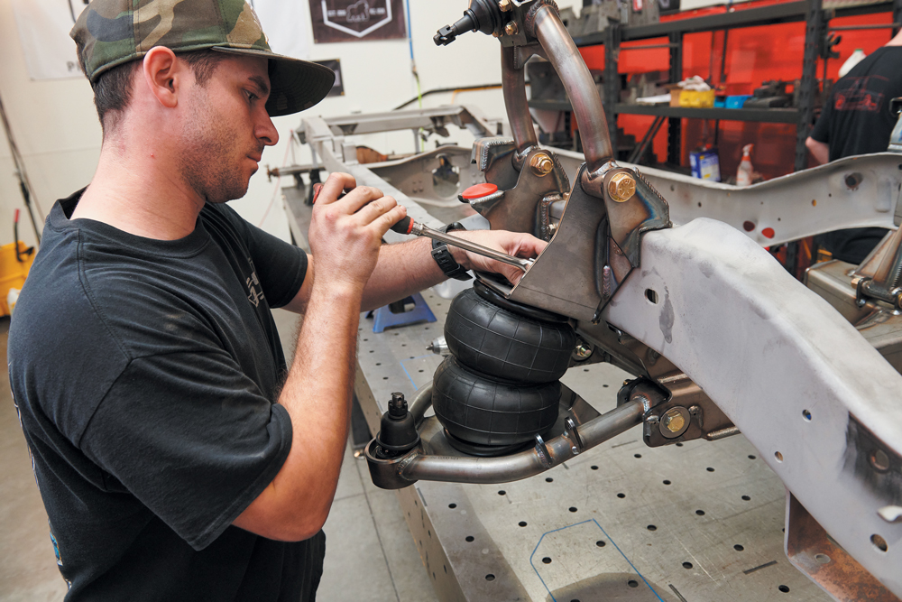
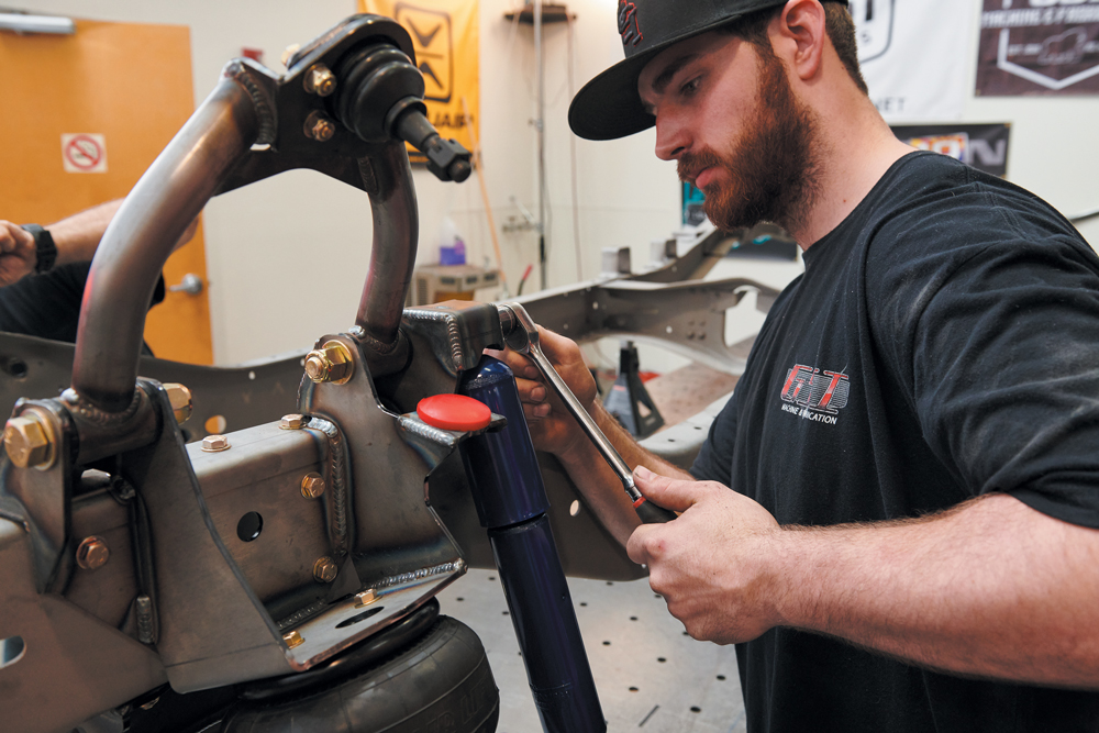
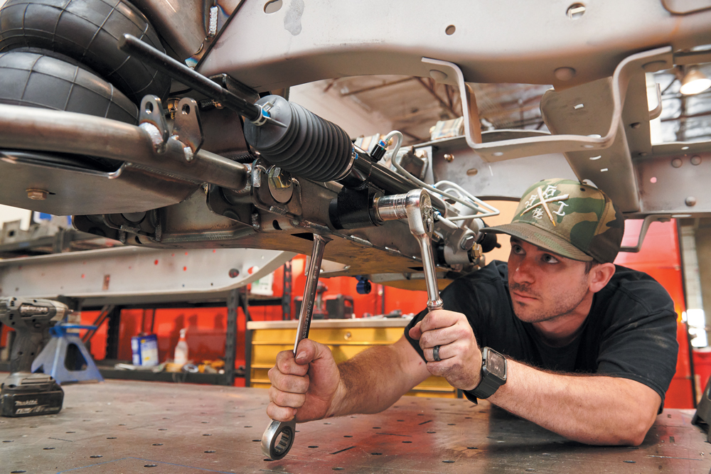
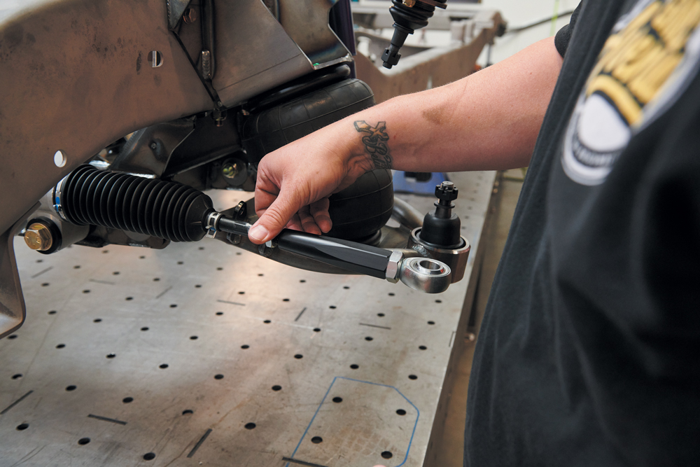
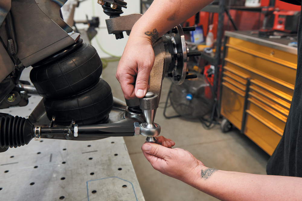
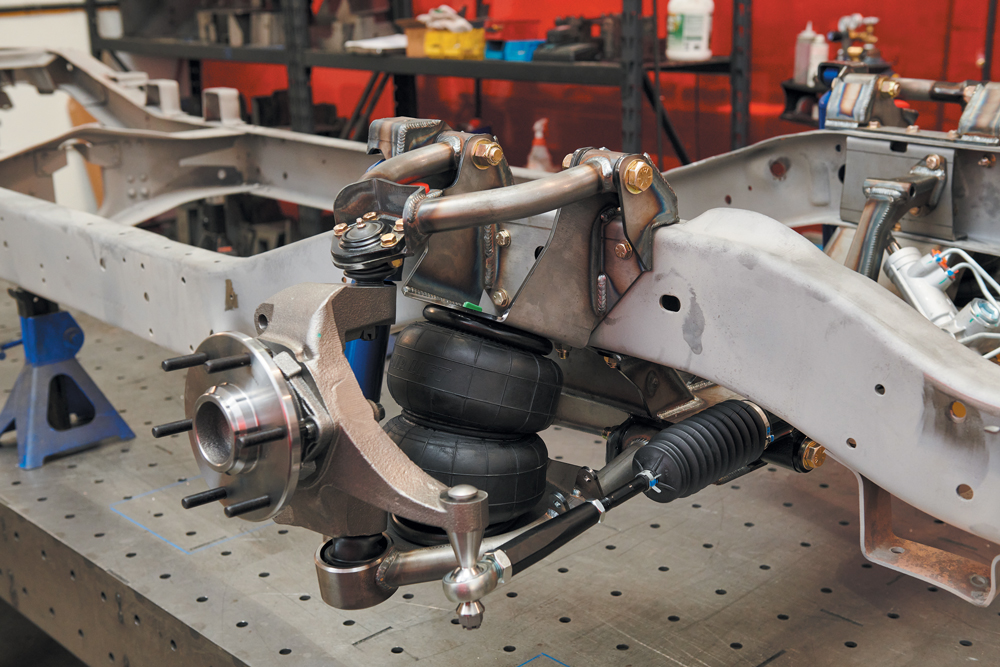
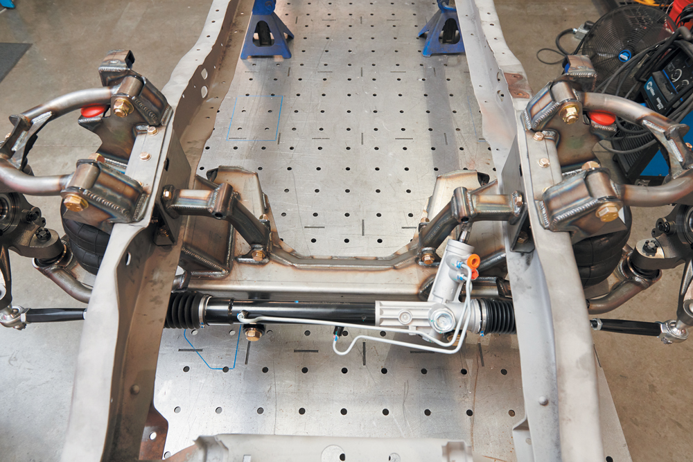
Now it’s time to install the assembled lower control arms using the GSI custom lower eccentric bolts and washers. The eccentric pivots allow for easy and quick alignment. Be sure to press the ball joints prior to install. The lower arms are passenger/driver specific. An easy way to tell is by looking at the sway bar tabs and shock mounts. Sway bar tabs go to the front of the vehicle, and the shock mount to the rear. Again, if their arms fit snug, a rubber mallet will do the trick.After the control arms are installed, we move to mounting the AirLift Dominator D2600 airbags to the lower control arms, cycle the arm up to meet the top of the bag to the upper mount and secure with two 3/8-inch bolts. Note: if this is final assembly, use a dab of Loctite on the airbag hardware as specified in the instructions.Install the shocks into the upper shock mount, then cycle the lower arm as needed to bolt the lower shock to the lower shock mount. There are a few shock options available from GSI: the standard gas shock (shown) or the upgraded Ridetech smooth body adjustable shock.Now it’s time to put on the brand-new power rack-and-pinion unit. GSI makes a solid aluminum bushing set to replace the rubber mounts that come standard with these racks. We will need to remove the rubber bushings prior to install. There are two sizes of aluminum bushings. The thick side goes toward the crossmember and the thin side to the front of the vehicle. There is a captured weld nut on one side of the crossmember, while the opposite side will use a bolt and nyloc nut. There is a window cut into the bottom side of the crossmember giving access to the nyloc nut to be installed.Thread on the GSI billet tie rod adapter kit. This will connect the rack-and-pinion to the spindle using an aluminum threaded sleeve, FK Heim joint, billet stainless steel misaligns, jam nuts, cotter pins, castle nuts and a custom heat treated GSI taper bolt. This tie rod kit is nice because it requires no modification to the spindle. It also corrects bump steer issues commonly found in air-ride suspension systems.
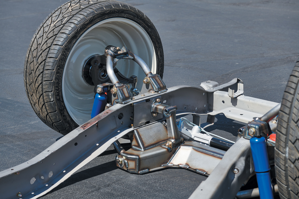
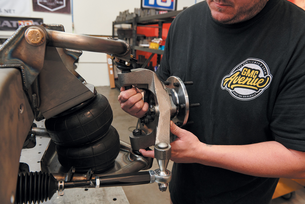
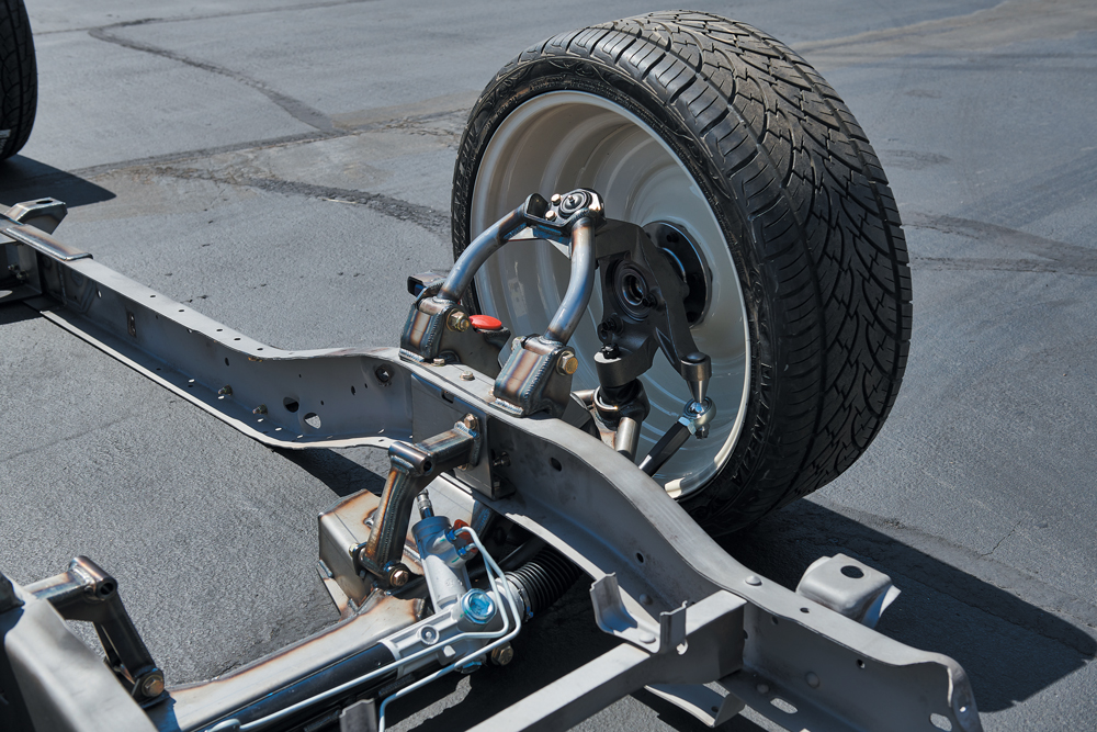
Now we will install our CPP drop spindles. We used the company’s new x10 spindle in this application, but GSI designed the frontend around any type of CPP spindle for C10, which you can choose at time of purchase. We drop the spindle onto the lower ball joint, swing the upper control arm down into place, install and tighten the castle nuts, and then, using the GSI taper bolt from the steering kit, we connect the spindle steering arm to the Heim using the misalignment spacers, taper bolt and castle nuts. Your spindle choice is determined by wheel size. GSI’s sales team can advise on what spindles are needed per application.Here you can see the passenger side is fully assembled. This particular combination will lay the frame on a 31-inch tall tire when paired with a CPP drop spindle and a wheel with a 20-inch or larger diameter.We successfully completed the install. Spindle to spindle. Ready to hit the ground. All hardware is tight, and work has been double checked. Now we are ready to pull it off the table.The frontend kit is installed and shown here on a 22-inch wheel with a 265/35/22 tire, laying frame flat on the ground. Improved geometry, power rack-and-pinion steering, disc brake spindles, easy install, using all simple hand tools. It doesn’t get any better than that. GSI has the most complete kit on the market that will take you from stock, to slammed in a matter of hours. Stay tuned as we continue this build! Next up will be the GSI ’63-’72 air-ride back half. Follow this build on Instagram using the hashtag #62suckerpunch on @gsi_machineandfabrication.
We use cookies to enhance your browsing experience, serve personalized ads or content, and analyze our traffic. By clicking "Accept All", you consent to our use of cookies. Visit our Cookie Policy for more info.
 streettrucks
.
November 11, 2020
.
C10 Builders Guide
.
streettrucks
.
November 11, 2020
.
C10 Builders Guide
.


Share Link