Brake Upgrade Kit for ’76-’79 F-250 Dana 44 & 60 Axles 4x4s
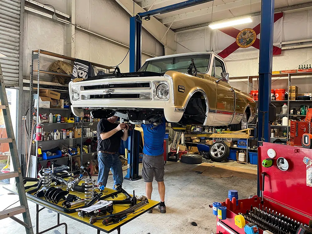
We have a highboy, and we want better brakes. That is what started the crew at PRD Design down the path of developing a brake upgrade kit. Overall, the current brake upgrade market for ’67-’79 F-250 4x4s is primarily made up of part swaps for later-model OEM axles, like the disc brake Dana 44s from 1976-’79 F-250 trucks. There are also options to swap in late-model Super Duty axles.
While these options work, they either require a fair amount of chassis and suspension modifications or, even if they bolt in like the 1976-’79 Dana 44s, still leave you with 1970s technology, leaving many owners wishing they could go the next step to modern brakes.
We faced this dilemma for a customer and his 1969 F-250 4×4 receiving a new Coyote swap and several other upgrades. We opted for a 1976 Dana 44 factory disc brake axle to provide upgraded brakes for the extra horsepower but were still unsatisfied. The original calipers needed replacing; the only real options were remanufactured parts of unknown origin. That still leaves you with big, chunky, heavy parts that still scream of 1970s engineering.
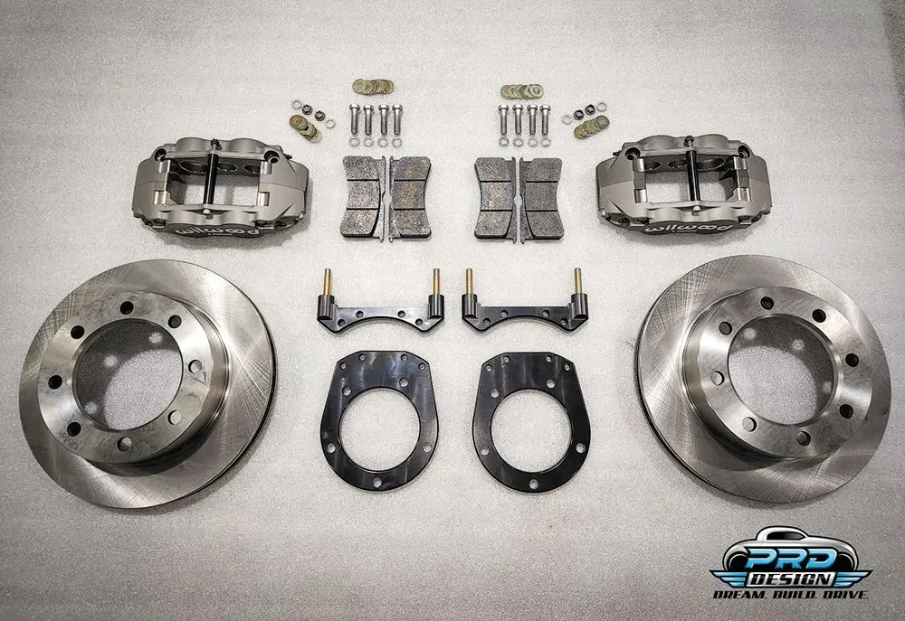
There must be something else available. We couldn’t find it, so we decided to make it. Utilizing proven caliper technology from Wilwood Engineering, we set out to make a kit that would fit over a stock-size brake rotor inside a 16-inch Ford steel wheel to keep that classic 4×4 look. After R&D and a few sets of prototype brackets, our brake kit was complete.
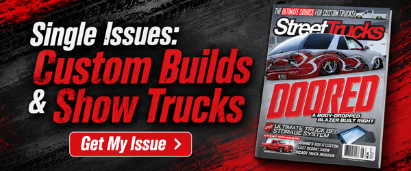
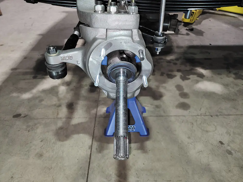
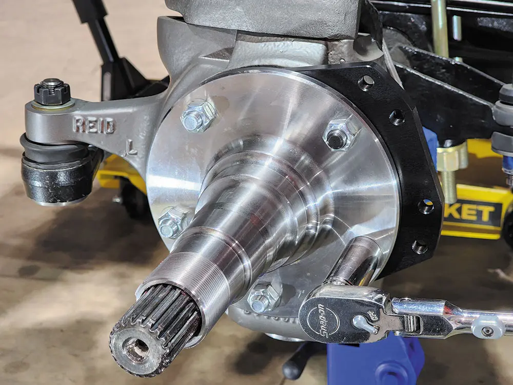
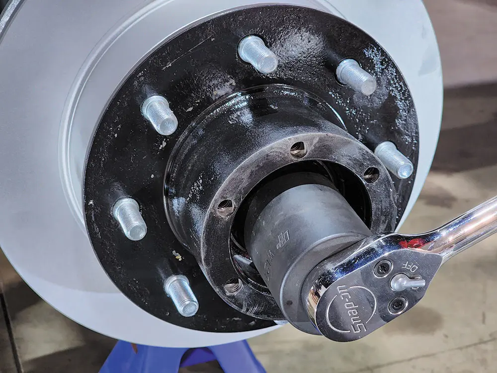
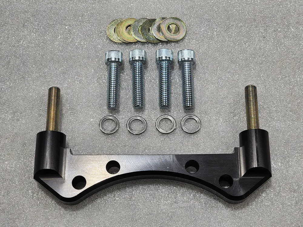
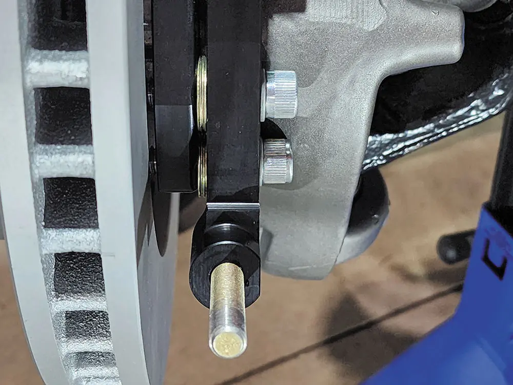
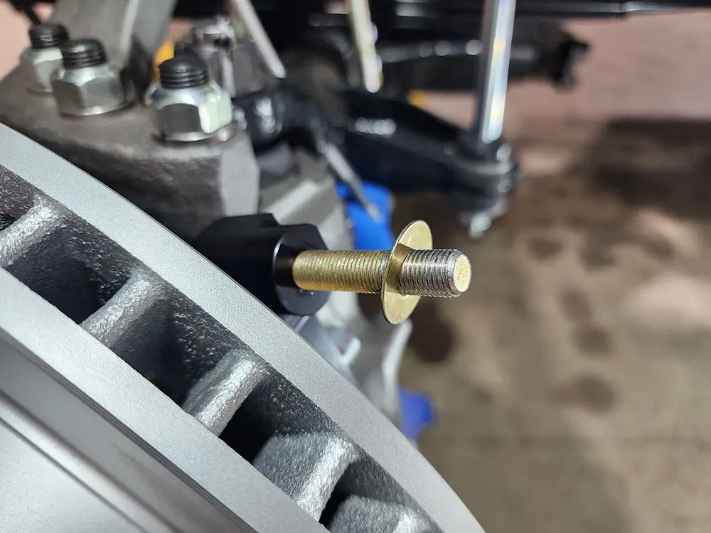
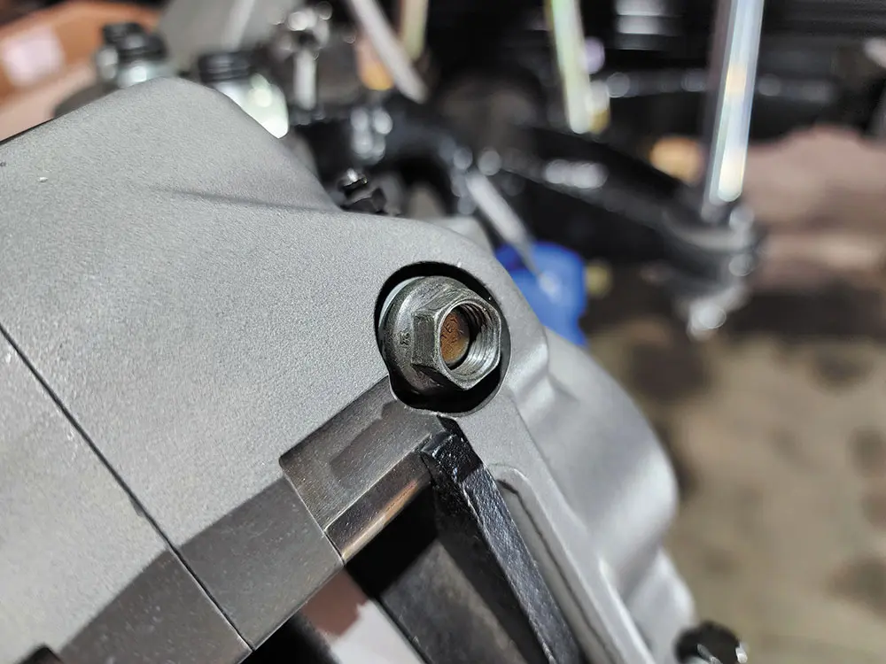
01. Disassemble the original front brakes: Raise the front wheels off the ground and support the front suspension according to the manufacturer’s instructions. Remove the front wheels and completely disassemble the stock brake system to the bare knuckle. The wheel studs will need to be pressed out of the OEM hub. Now is the time to inspect and replace any worn axle shaft components, ball joints, bearings, and spindle mounting studs. At this time, clean and de-grease the spindle and knuckle mounting surfaces.02. Install the flat mount bracket as shown, install the OEM spindle over the bracket, and secure it temporarily with OEM nuts. Inspect that the bracket fits squarely against the mounting surface of the knuckle and is free from interference from casting irregularities, machining ridges, burrs, etc. Remove the nuts one at a time, apply red Loctite 271 to the bolt threads, and torque nuts to OEM specification.2a03. Install the new brake rotor onto the OEM hub according to the OEM specifications. (Note: New wheel studs are recommended.) Install the hub and rotor assembly onto the spindle following OEM specifications and torque specs. Now is also a great time to install new wheel bearings and seals.04. Install the caliper mount bracket with clean, dry threads on the mounting bolts initially. Orient the bracket as shown, and install using the socket head mounting bolts and 3/8ths washers. Place two 0.035-inch-thick shims between the flat and caliper brackets on each bolt. Align and temporarily tighten the mounting bolts. Later, after the caliper alignment has been checked, the mount bolts will be secured using red Loctite 271.4a4b05. This kit contains distinct right- and left-hand calipers that must be mounted in the specific direction to the front of the truck, as noted by the arrows machined into the outside of the caliper. Place one 0.035-inch-thick shim on each stud, as shown. Mount the caliper onto the bracket using lock nuts and washers. Temporarily tighten the lock nuts. Ensure that the caliper is mounted so the largest pistons are at the rotor exit end of the caliper in relation to the direction of the rotor. View the rotor through the top opening of the caliper.
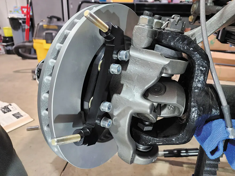
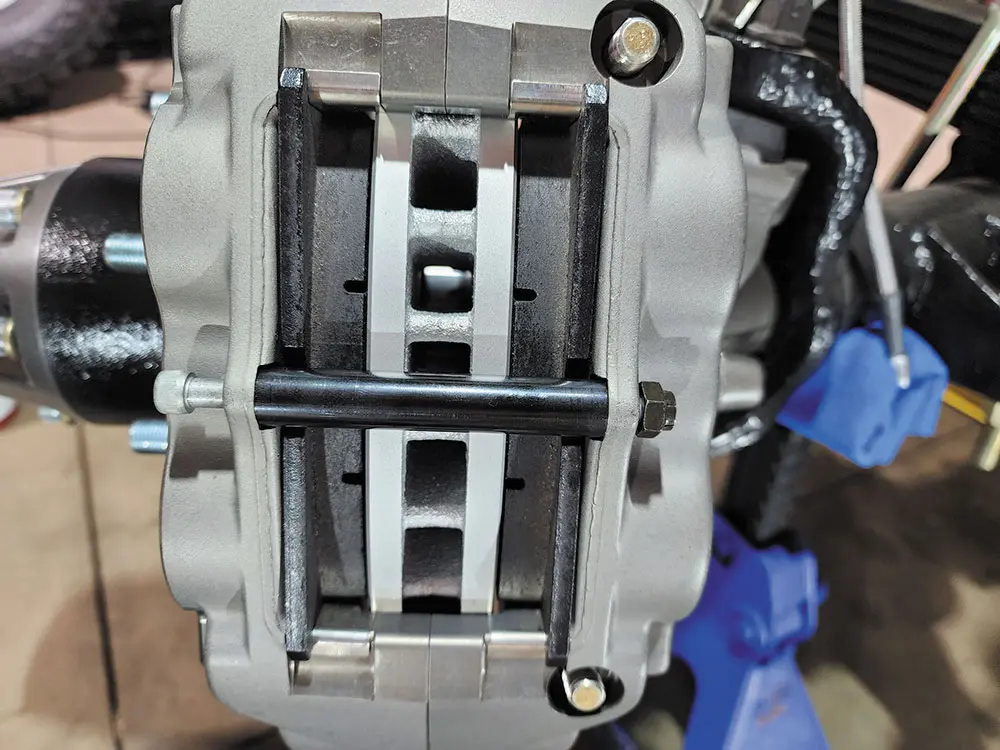
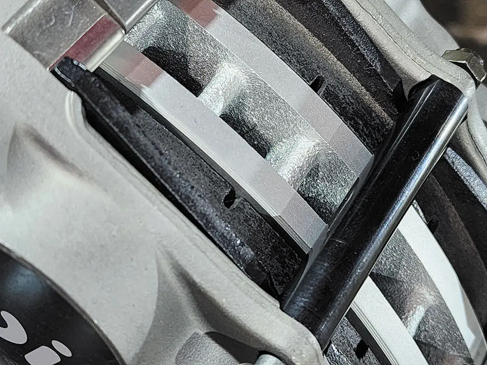
The rotor should be centered in the caliper (Photo 7). If not, adjust by adding or subtracting shims, 0.016-inch or 0.035-inch, between the spindle bracket and caliper bracket. Always use the same amount of shims on each of the four mounting bolts. Once the caliper alignment is correct, remove the bracket mounting bolts one at a time, apply red Loctite 271 to the threads, and torque to 35 lb-ft. Install the brake pads into the caliper by removing the caliper center bridge pad retainer bolt, nut, and tube.
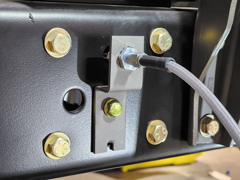
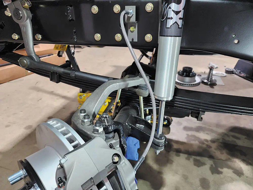
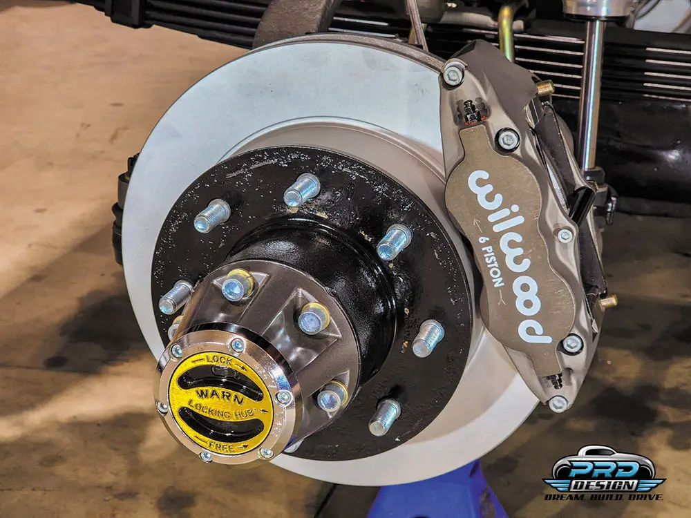
Insert the brake pads into the caliper, with the friction material facing the rotor. Check that the top of the brake pad is flush with the outside diameter of the rotor. If not, adjust by adding or subtracting shims between the caliper and the bracket. After setting the caliper pad height, torque the caliper lock nuts (15) to 30 lb-ft. Secure the brake pads in place with the center bridge pad retainer tube, bolt, and locknut. The locknut should be snug without play in the bolt or tube. Be cautious not to over-tighten.5a5b5c06. OEM rubber brake hoses cannot be adapted to the calipers. The caliper inlet fitting is a 1/8-27 NPT. Use PTFE tape on pipe threads to seal the caliper properly. Install the stainless steel braided flex line hose kit. The installer is responsible for proper routing and ensuring adequate clearance and retention for brake hose components.6a07. The completed kit in its final form.
What specific parts differ in Dana 44 axles from different manufacturers?
Differences in Dana 44 Axle Parts Between Manufacturers
When examining Dana 44 axles across various manufacturers, it’s crucial to recognize that they have different specific parts that set them apart. While the core assembly might seem similar, key differences exist.
Key Parts that Differ:
Wheel Hubs:
Some vehicles use six-lug hubs, while others employ eight-lug configurations. The number of lugs affects the hub’s compatibility with different wheel types.
Brake Components:
Brake systems can vary significantly. Some axles come with drum brakes, while others use disc brakes. This variation influences stopping power and maintenance requirements.
Gear Ratios:
The gear ratio, determining the balance between torque and speed, is another differing component. Different manufacturers may choose ratios to match their vehicles’ intended performance.
Spring Pads and Shock Mounts:
Placement and style of spring pads and shock mounts can differ, influencing how the axle interacts with the vehicle’s suspension system.
Understanding these differences can be crucial for anyone looking to swap or upgrade parts on their Dana 44 axle. It ensures compatibility and optimal performance for your specific vehicle.
What differences exist between Ford, GM, Dodge, and Scout Dana 44 axles?
Differences Between Ford, GM, Dodge, and Scout Dana 44 Axles
When it comes to Dana 44 axles, not all are created equal across different vehicle manufacturers. Although they share a common base design, there are notable differences you need to be aware of.
Variations in Designs
Ford Dana 44 Axles: These typically feature unique steering knuckle designs and mounting configurations. Ford also tends to have specific brake setups, influencing both performance and compatibility with other vehicle systems.
GM Dana 44 Axles: Known for their diverse applications, GM’s versions often differ in wheel hubs, offering either six or eight lug patterns. The brake systems can vary between drum or disc, depending on the vehicle model and year.
Dodge Dana 44 Axles: Dodge axles have their own steering knuckle designs and usually distinct differential housings. They also differ in terms of gear ratios and spring pad placements, affecting their interchangeability with other brands.
Scout Dana 44 Axles: International Scout vehicles have Dana 44 axles with their own unique setups, particularly in gear ratios and mounting points. The brake components also stand apart, reflecting the specialized nature of Scout vehicles.
Key Differentiators
Steering Knuckles: Positioning and design vary significantly, impacting handling and compatibility.
Wheel Hubs: Different lug patterns (six or eight lugs) make a big difference in the types of wheels you can use.
Brake Systems: Choices between drum and disc brakes affect stopping power and maintenance requirements.
Gear Ratios: These impact vehicle performance and are tailored to match the needs of each manufacturer’s models.
Mounting Points: Variations in spring pad and shock mount placements can make cross-brand swaps more complex.
Understanding these differences is crucial for anyone looking to modify or repair vehicles with Dana 44 axles. Each brand has tailored the Dana 44 to suit its specific engineering goals, resulting in substantial differences despite the shared Dana 44 designation.
What expert insights do Joel Snider and Joe Shaff provide about Dana 44 swaps?
Curious about Dana 44 swaps? Joel Snider and Joe Shaff, experts from Stage West 4-Wheel Drive, shed light on this topic. They address common misconceptions, particularly about interchangeability and the simplicity of swapping parts.
Here’s what they reveal:
Interchangeability: Not all Dana 44 axles are alike. Variations in dimensions, bolt patterns, and mounting points mean that direct swaps aren’t always feasible without modifications.
Swapping Ease: Simply put, swapping Dana 44 axles can be complex. Individual differences in each axle type can pose unique challenges, requiring specific adaptations and careful planning.
According to Snider and Shaff, these insights aren’t just limited to GM vehicles. Many of these challenges are also relevant to other brands like Dodge and Ford, making their advice invaluable for a broader audience contemplating similar projects.
Do the issues with Dana 44 part interchangeability apply to Dodges and Fords as well?
Absolutely, the interchangeability problems with Dana 44 parts extend beyond just one manufacturer. While it’s a common misconception that all ’78-and-older Dana 44 models are basically the same from the steering knuckles inward, this isn’t true. Each brand—whether it’s GM, Dodge, or Ford—has distinct variations.
Key Points on Dana 44 Part Interchangeability:
Brand-Specific Differences:
GM Dana 44: General Motors Dana 44s have unique design elements and dimensions that set them apart.
Dodge Dana 44: Dodge variants also have their own specific configurations, incompatible with GM parts.
Ford Dana 44: Ford’s Dana 44s come with another set of differences that further contribute to the interchangeability puzzle.
Common Misconception:
Many believe that Dana 44s from these brands are interchangeable, but in reality, each has distinct engineering specifications that affect compatibility.
Shared Issues:
Although focused mainly on General Motors, the challenges in part interchangeability are prevalent across other brands like Dodge and Ford as well.
Understanding these nuances is crucial for anyone looking to swap or replace parts in their Dana 44 axles. Always check the specific brand details before assuming compatibility.
Are all ’78-and-older, open-knuckle General Motors Dana 44 axles identical?
It’s a widespread belief that all ’78-and-older, open-knuckle GM Dana 44 axles are essentially the same, particularly when you look at them internally from the steering knuckles inwards. This notion, however, is a bit misleading as it oversimplifies the differences and ignores some crucial distinctions.
Key Differences
While it’s true that these axles share many common features, there are several variations worth noting:
Wheel Hubs: Differ depending on whether they have six or eight lugs.
Brake Components: Can either be drum or disc brakes.
Gear Ratios: These can vary widely.
Mounting Points: Spring pads and shock mounts might also differ slightly.
Common Misconceptions
One of the biggest myths is that the axlehousing dimensions, axleshafts, U-joints, and steering knuckles are identical across all models from this era. This is not accurate. Even within the same general type of axle, there can be subtle yet significant differences.
Swapping Components
Another misconception is the ease of swapping parts, especially upgrading from drum brakes to disc brakes. While many think this is a straightforward task, it often involves more adjustments and challenges than anticipated. Compatibility is not always guaranteed, requiring careful consideration and, sometimes, custom modifications.
Conclusion
Although ’78-and-older, open-knuckle GM Dana 44 axles share many similarities, they are not universally identical. The truth is in the details—wheel hubs, brake parts, gear ratios, and mounting points can vary enough to make straightforward swaps more complex than they might initially appear.
What challenges can arise when swapping later-model disc brakes onto an earlier open-knuckle drum brake Dana 44axle?
Overall, the current brake upgrade market for ’67-’79 F-250 4x4s is primarily made up of part swaps for later-model OEM axles, like the disc brake Dana 44s from 1976-’79 F-250 trucks. There are also options to swap in late-model Super Duty axles. While these options work, they either require a fair amount of chassis and suspension modifications or, even if they bolt in like the 1976-’79 Dana 44s, still leave you with 1970s technology, leaving many owners wishing they could go the next step to modern brakes.
However, it’s important to recognize the challenges that come with these swaps. Issues with interchangeability and ease of swapping are common. Experts in the field, like Joel Snider and Joe Shaff of Stage West 4-Wheel Drive, have pointed out that these challenges are not just limited to GM 44s but can also apply to other brands such as Dodge and Ford.
Key Challenges:
Interchangeability: Not all parts are directly compatible, making it necessary to identify the right components for your specific model.
Ease of Swapping: Many swaps require significant modifications to the chassis and suspension, which can be time-consuming and costly.
Technological Limitations: Even with successful swaps, you might still be dealing with outdated 1970s technology, which doesn’t meet modern performance standards.
By understanding these challenges, you can better prepare for the complexities involved in upgrading your brake system. This knowledge can help you make informed decisions, whether you opt for later-model OEM axles or consider more modern solutions.
We use cookies to enhance your browsing experience, serve personalized ads or content, and analyze our traffic. By clicking "Accept All", you consent to our use of cookies. Visit our Cookie Policy for more info.
 BRYCEN SMITH
.
May 26, 2023
.
HEADLINE
.
BRYCEN SMITH
.
May 26, 2023
.
HEADLINE
.


Share Link