As the C-10 market continues to grow, innovation must grow with it. We have made huge leaps in the quality of our current crop of classic truck metal and that is due, in part, to ever-increasing support from a wide array of aftermarket companies. As the aftermarket creates more accessible truck parts, truck owners can focus on their dreams without feeling overwhelmed with thoughts of “How am I going to do that? I don’t know how to do bodywork, wiring, welding, etc.” Our custom truck world requires innovation that fuels the imagination and ignites motivation.
During SEMA 2015, we came across one such product that was a perfect example of “imagination fuel.” No stranger to the classic truck market, McGaughy’s suspension was displaying a fully painted C-10 rolling chassis filled with all new parts that had people lined up every day full of questions. Having focused on the lifted truck market, of late, it was awesome to see such a huge leap in lowering and performance product design from the long-standing suspension company. We had questions of our own, so we sat down with company head, Steve McGaughy.
C-10 Builder’s Guide: Tell us about these 1963-87 C-10 parts you’re releasing.
Steve McGaughy: We decided it was time to add some serious performance to our already long list of lowering products and brakes, so we created a new drop cross member system front and rear with custom control arms and trailing arms. Everything is set up for coil-over shocks to get these old trucks to handle like modern sports cars.
C10BG: Is it one whole kit or are you offering parts separately if someone is building in stages? For example, could a truck owner do the front now and the rear later if they choose?
McGaughy: It is absolutely set up that way. We would love to have everything sold as one whole system to maximize performance, but we realize that many truck owners have to work their way up as time and money permit.
C10BG: It looks like there are plenty of adjustable components in the system. Give us some details.
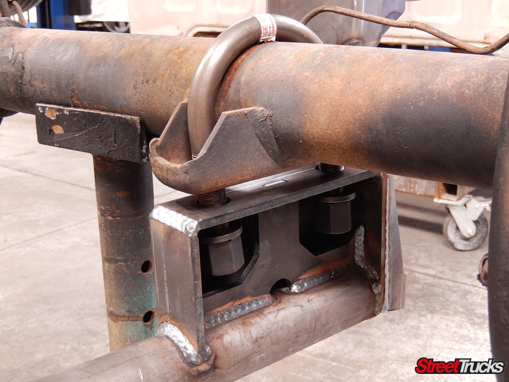
McGaughy: The front track is 1-inch narrower to allow wider front tires. To make alignments a smooth operation, we added eccentric cams on the upper arms. That way the owner can dial-in camber and caster to specs. The trailing arms use Johnny joints to allow good street manners, but we made them adjustable to get the rear axle perfectly square under the frame. If you look underneath, you’ll see that that the rear track bar pedestal has a number of mounting holes to correctly function at a multitude of ride heights.
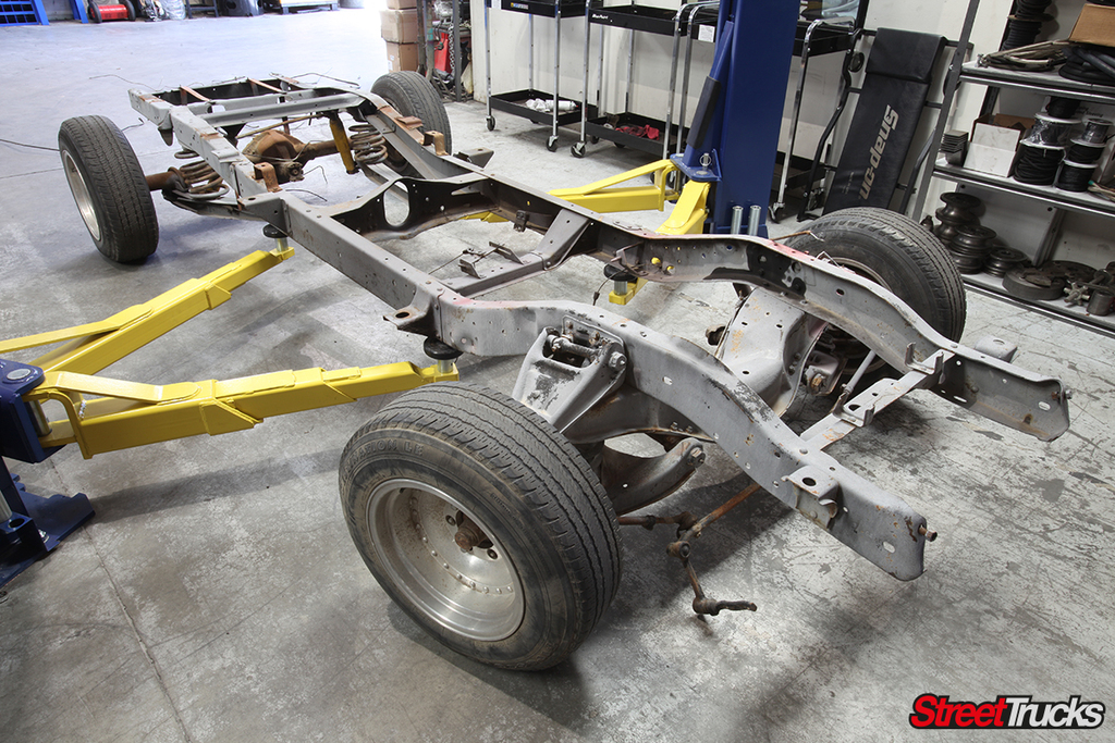
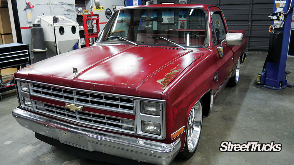
It should come as no surprise, but we were sold and wanted a look behind the curtain, so Steve invited us up to his place in Fresno, California, to participate in a full chassis transformation. Once we arrived, we marveled at the array of perfect project trucks Steve had to choose from, but we were pulled back to reality when he informed us that a suitable donor chassis was on the lift and ready to go. Follow along with us we take a 1963-66 chassis and turn it into a canyon-carving performer with McGaughy’s Suspension.
This 1964 chassis was no longer going to be a Central California ranch hand. Soon it would be ready for road course duty.
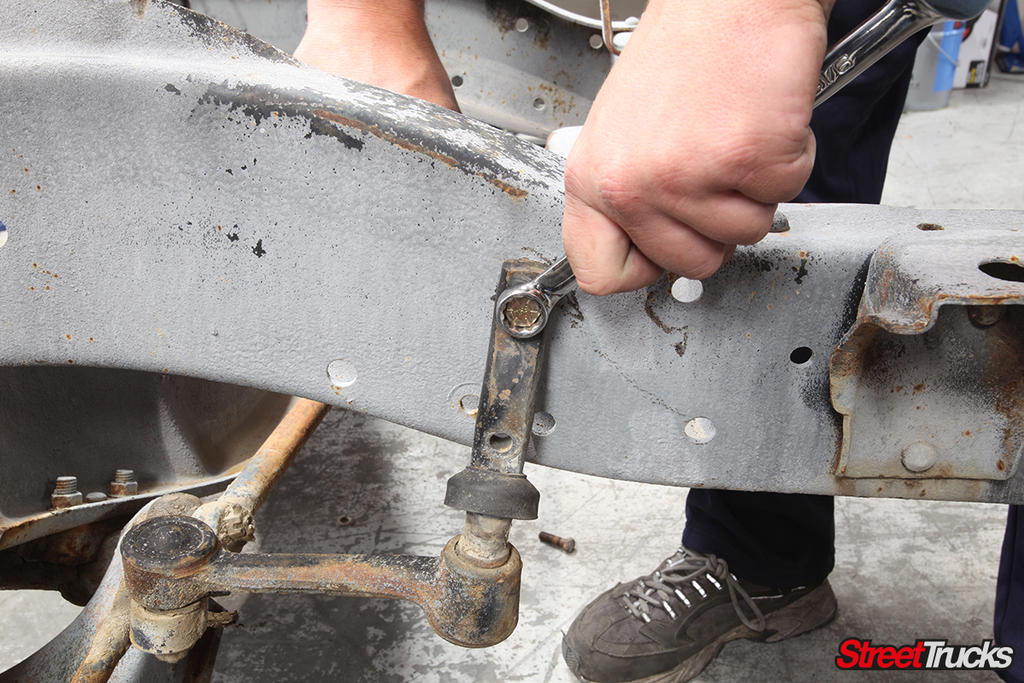
Basically, nothing was going to be reused except the frame itself, so teardown went quickly, since most of the parts on the chassis were completely worn out. The steering box and idler arm were unbolted from the rails first.
Next up were the upper shock bolts and every fastener holding the original front cross member to the front of the frame.
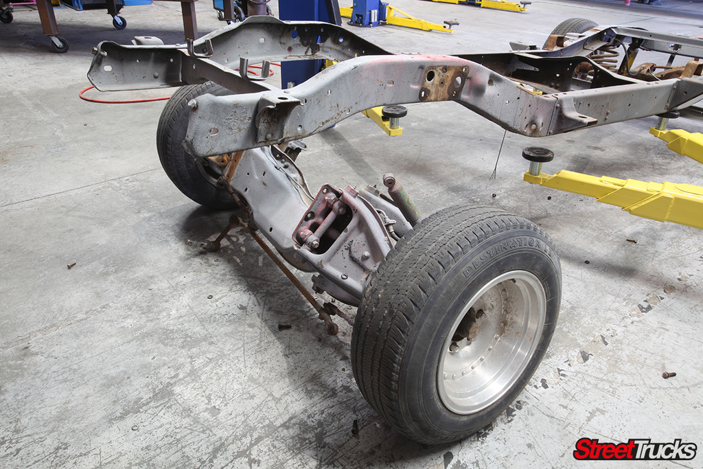
As you can see, the front suspension wasn’t torn apart. With everything unbolted, the hulking mass of metal was easily rolled out of the way.
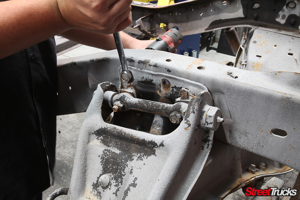
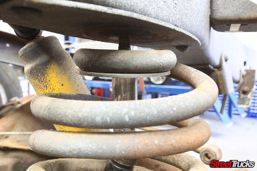
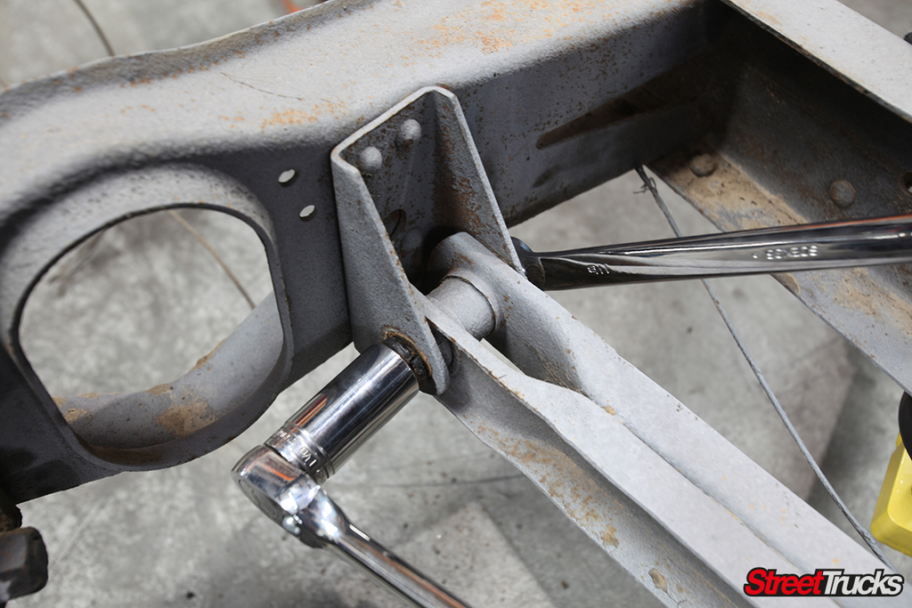
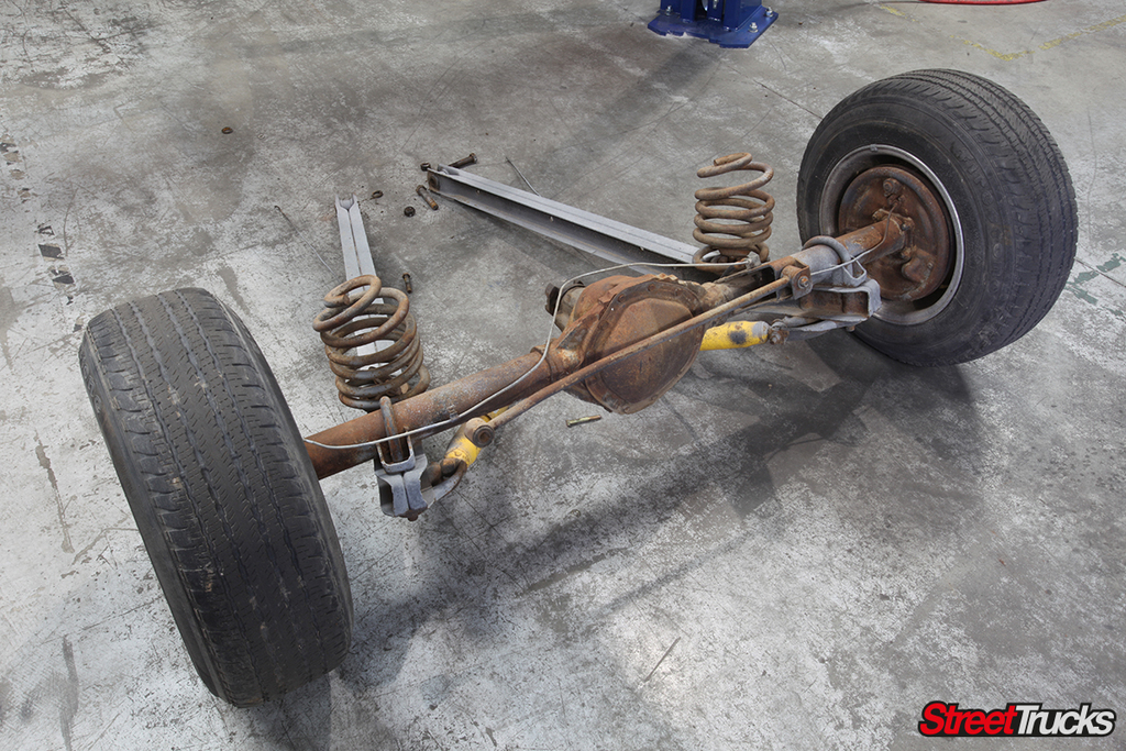
Removing the rear axle was done in similar fashion. If it touched the frame, it was only unbolted at this point. We removed the hardware from the upper shock mount followed by the upper coil mounts and the original track bar.
McGaughys had already pulled the fuel lines and brake lines from the chassis prior to our arrival, so after removing the bolts from the trailing arms, the rear axle was wheeled right out from under the frame.
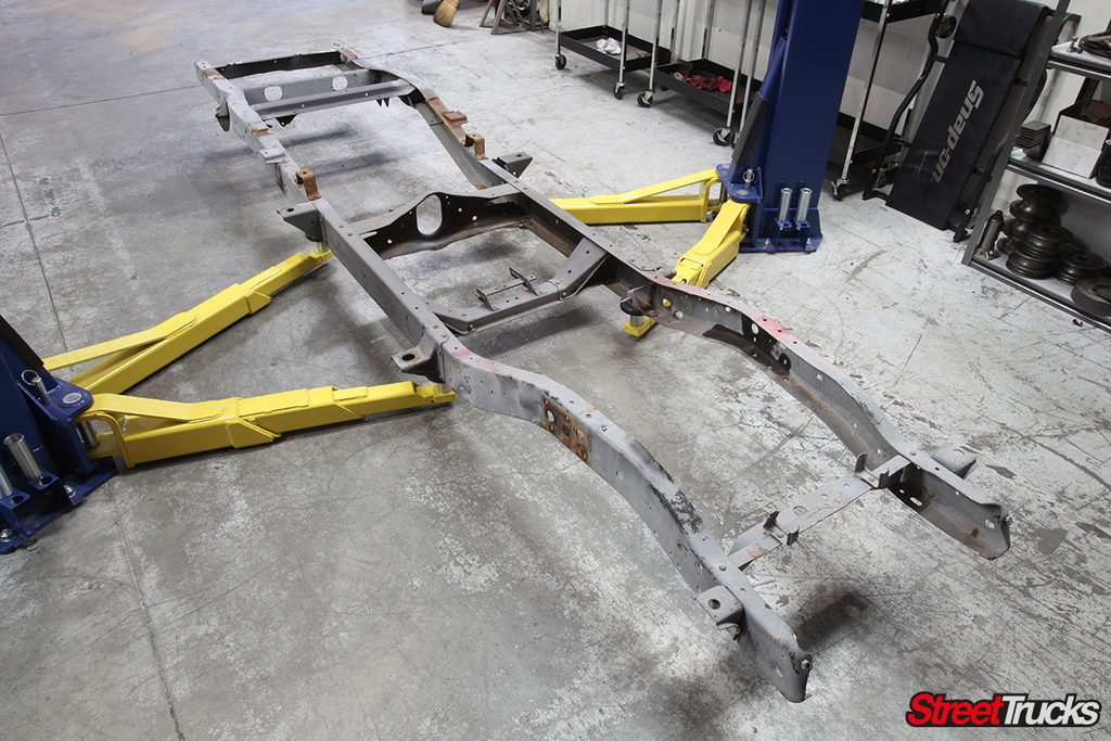
Now we were getting somewhere. After being subject to a lifetime of dirt, this frame was going to turn a corner, so to speak.
Installing the McGaughy’s System
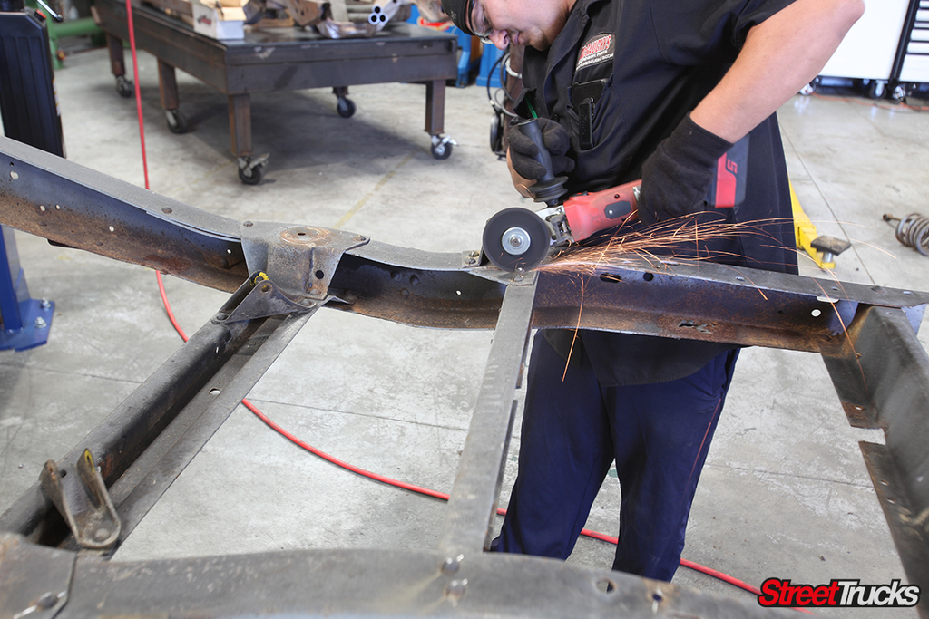
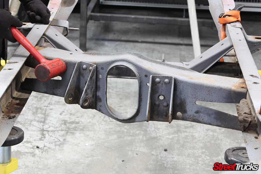
With the exception of the transmission cross member, the rest of the OEM bracing was riveted in place. We made short work of the heads by slicing a slot all the way in and knocking them off with an air impact chisel.
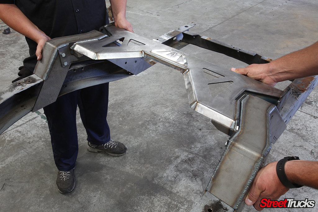
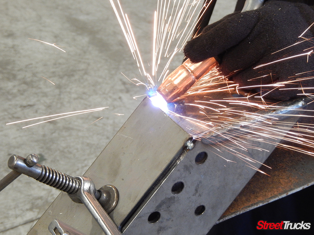
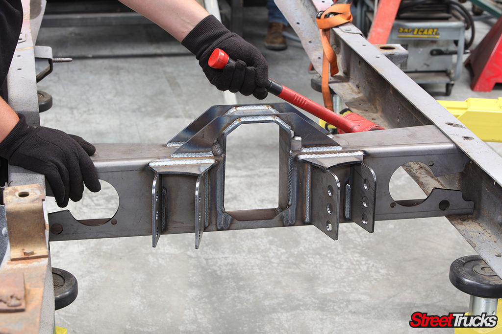
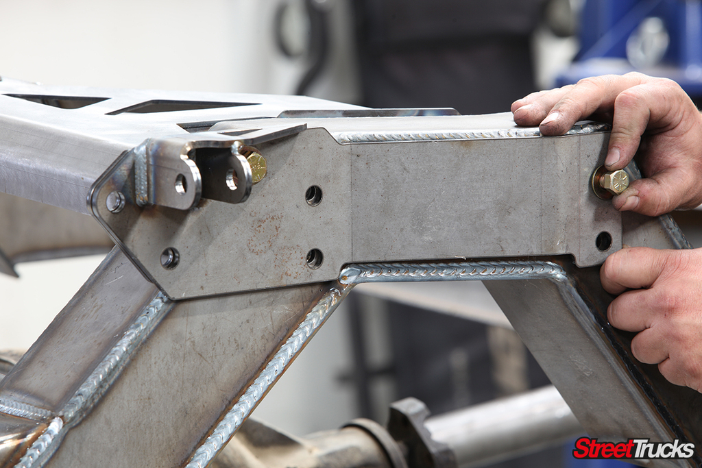
McGaughy’s designed the rear notches to be welded in place for maximum strength. The bridge was bolted in between each side first, and then the entire assembly was slid onto the frame.
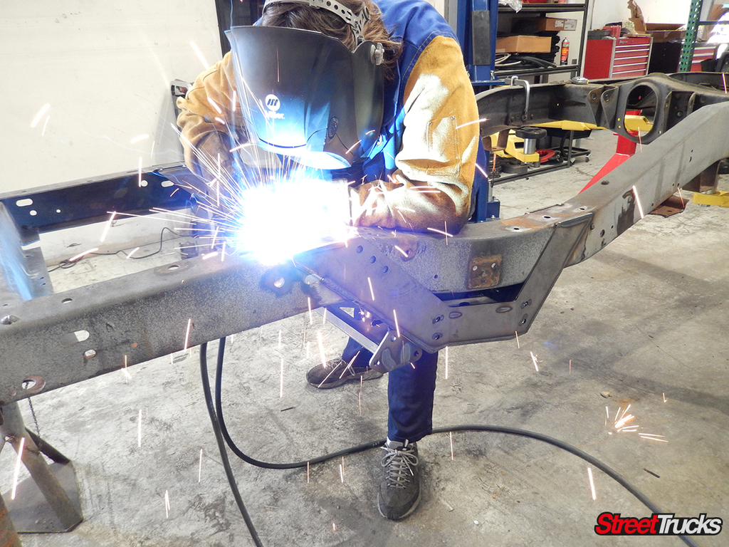
After taking measurements to locate the assembly properly, the outside of the notch was burned onto the frame. Since we had a bare frame to work with, it was a cinch to flip it over and weld the bottom, too.
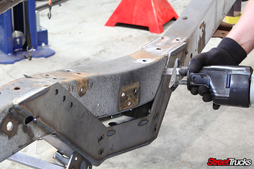
A sawzall made short work of slicing through the frame chunk inside the notch. We used the notch as a guide and cut as closely as possible to minimize cleanup afterwards.
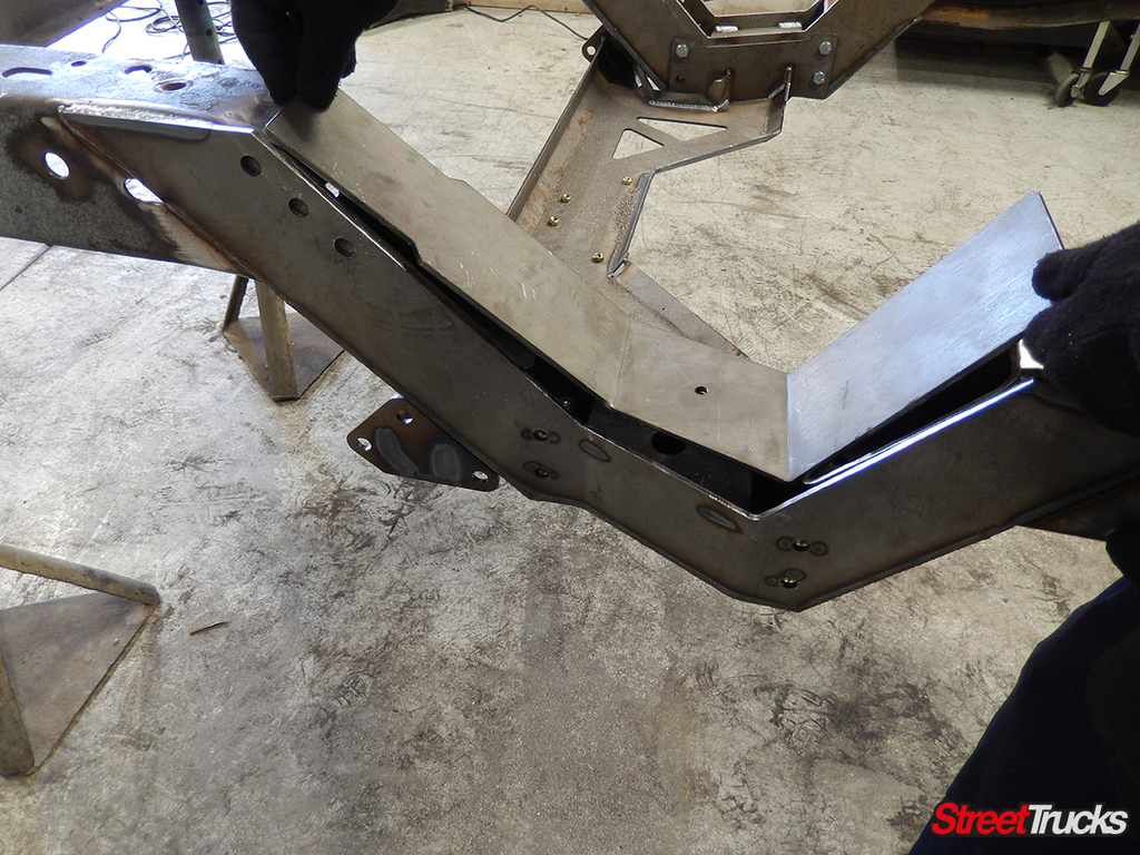
The plate that forms the underside of the notch needed to sit completely flush. Even though we cut as closely as we could, a minute with a flap wheel was necessary to ensure the best fitment.
Clamps were employed to hold the inner notch plate while we burned it into its final resting place. From here on out, the rest of the installation was a bolt-on affair.
Many of the mounting holes in the kit correspond to other components, but required drilling through the underlying frame. While the frame was still upside down, we mounted the new track bar frame pivot.
Be prepared for the frame to spring loose and move around a bit. These old trucks have had a long, hard life. After removing the rearmost frame support, we needed some assistance to realign the frame to meet the new McGaughy’s tubular replacement.
Keeping the frame from moving was a constant concern, which is why we only removed the necessary supports as we replaced them. Here, the original trailing arm cross member and transmission mount received their eviction notice.
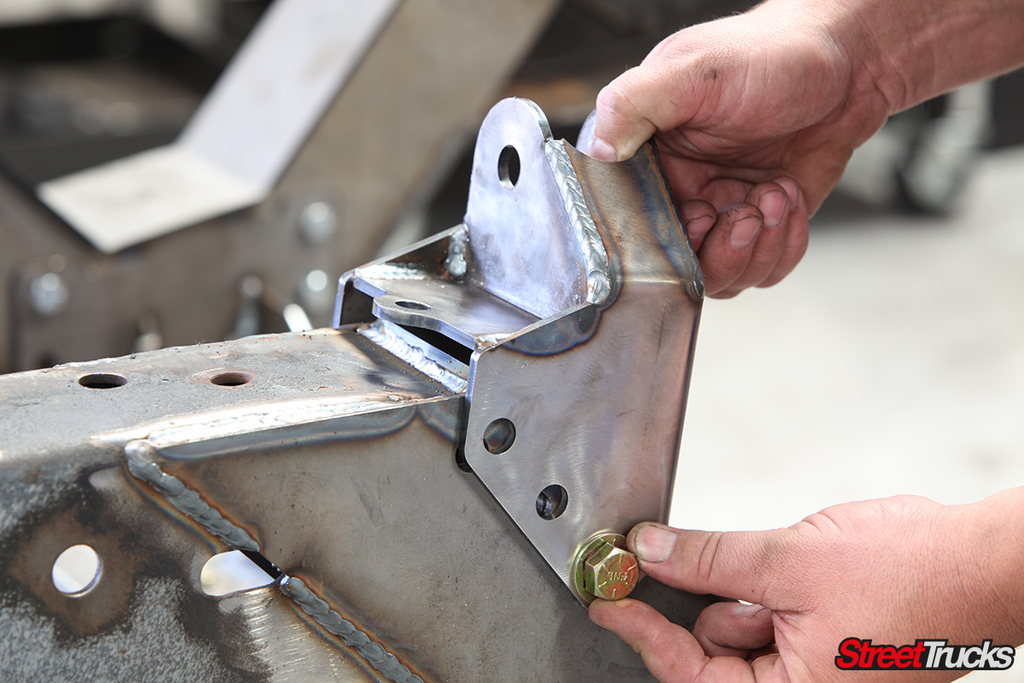
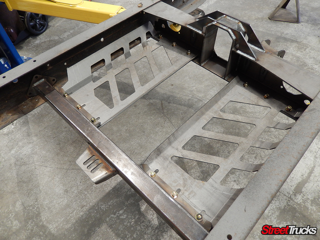
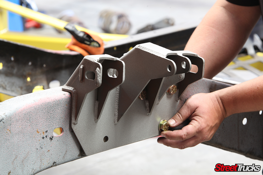
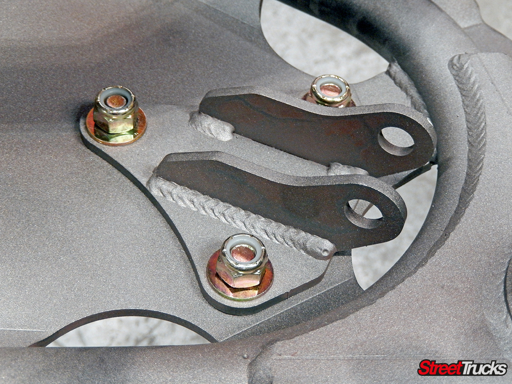
McGaughy’s has another trailing arm cross member in its catalog that many of you have probably used in the past. For this new system, an all-new design was built with additional gusseting for strength and adjustable trailing arm mounts to dial in pinion angle.
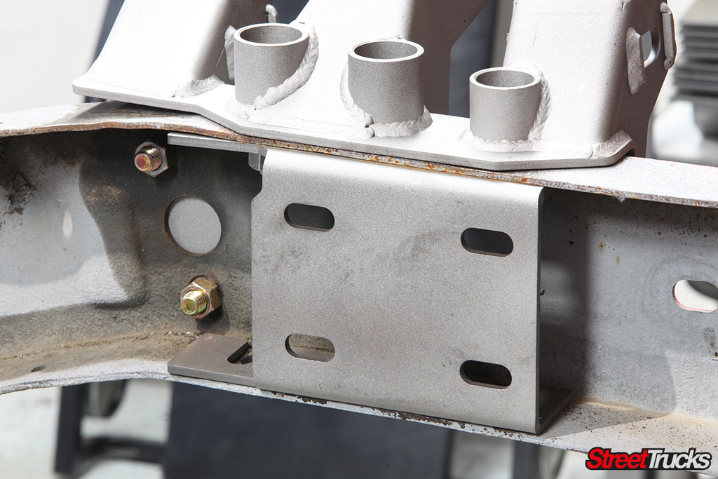
The new transmission mount was a straight-forward design and incorporated a GM-style mount. Twin belly plates locate between the transmission mount and the trailing arm cross member to tie the structures together. They were slotted at both ends to compensate for final transmission choice.
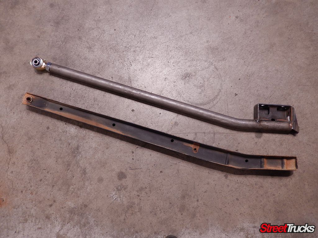
Compared side-by-side the new McGaughy’s trailing arms were light years better than the originals. Each new trailing arm was tipped with a 1 1/4-inch chrome-moly Johhny joint and finished with a fully gusseted axle pedestal and coil-over mount.
You have some choices when it comes to rear axle options. The trailing arms were designed specifically for the 10- and 12-bolt sticks that these trucks were originally equipped with, but McGaughy’s Suspension offers correct axle pads to allow a Ford 9-inch should the customer choose them.
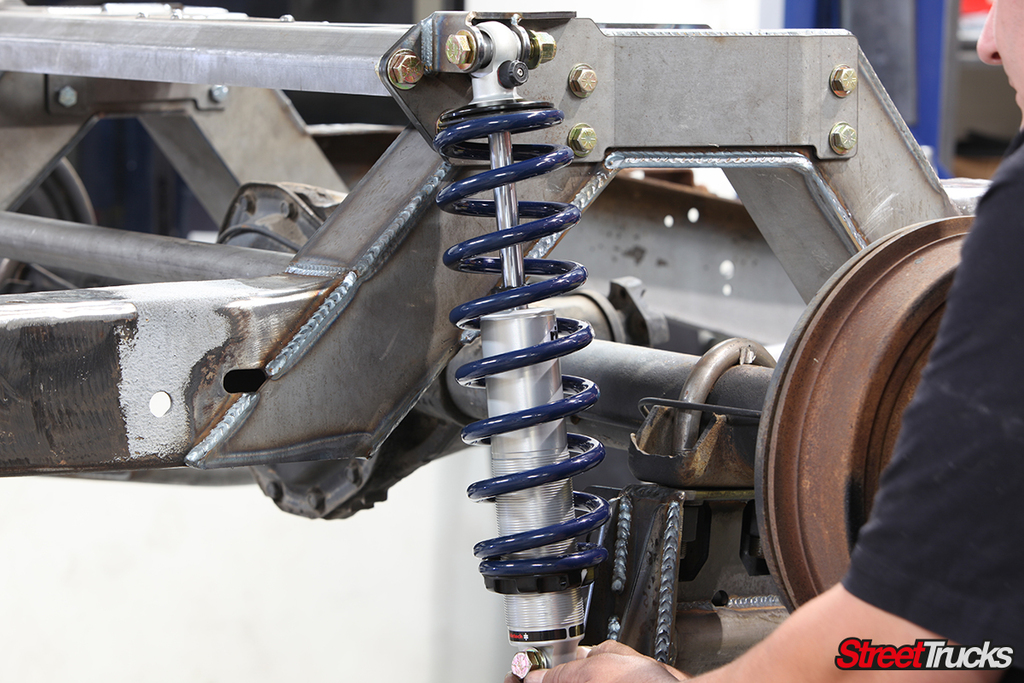
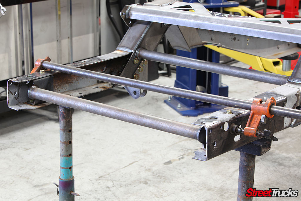
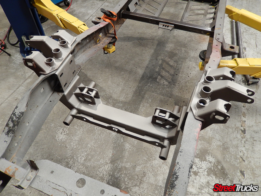
Coil-over mounts were bolted directly onto each side of the notch and added additional tie-in points between the welded notch and the bridge that were bolted on earlier.
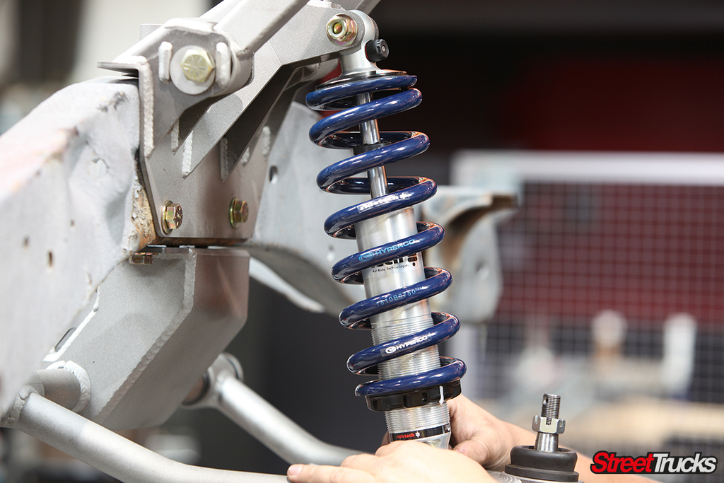
You have your choice of coil-over shocks, but McGaughy’s chose to run with Ride Tech’s 10-way adjustable HQ series shocks and coils.
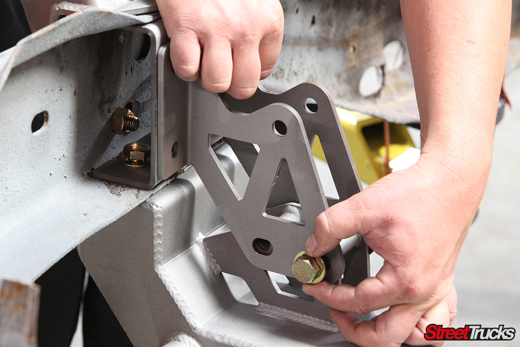
Upfront, we slipped the new upper control arm mount onto the frame. Again, most holes were original, but it was still necessary to drill through the frame to accommodate the rest of the hardware.
Inner frame doubler supports tied the top mount and lower cross member to the frame and provided additional support to the engine mounts.
In its current form, the new cross member rests just above the height of the frame, eliminating the biggest hang up to getting these trucks low to the ground. Integrated mounts on the front accept a Fox-body Mustang steering rack.
Engine mount footings add to the front structure because these frames require all the bracing they can get. Engine options run the full range of GM small-block, big-block and LS-based applications.
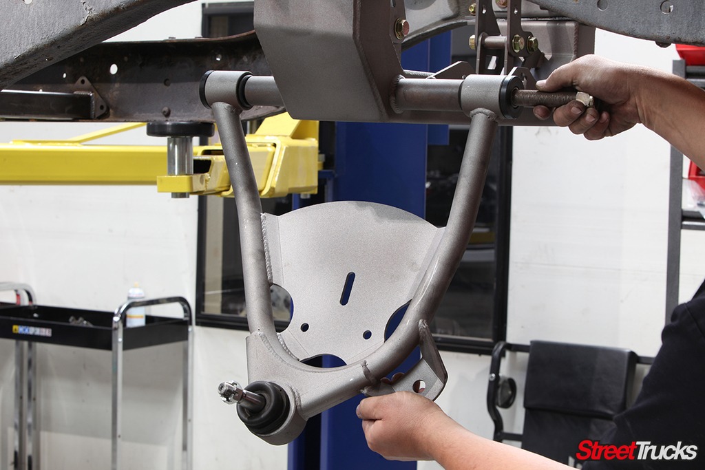
Tubular lower control arms, designed specifically for this application, suck the track width in an inch per side to allow extra room for wide tires.
A bolt-on lower mount gives the front coil-over a place to reside and allows McGaughy’s room for future expansion and alterations without redesigning a whole new control arm.
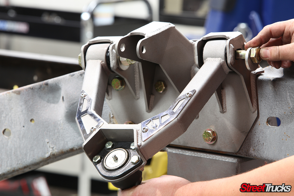
Two options exist for the upper control arm. The first is a basic round-tube design to match the lower control arm, or this square-tube version fit with trick polished steel inserts. You can see the choice we made; these just looked too cool to pass up.
More of Ride Tech’s awesome HQ series coil-overs were mounted between the McGaughy’s control arms.
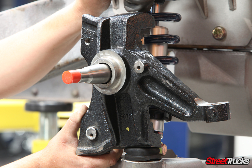
A dizzying array of spindle and brake options can be chosen for your kit. We went with these modified 2 1/2-inch drop spindles to allow larger brakes to be used.
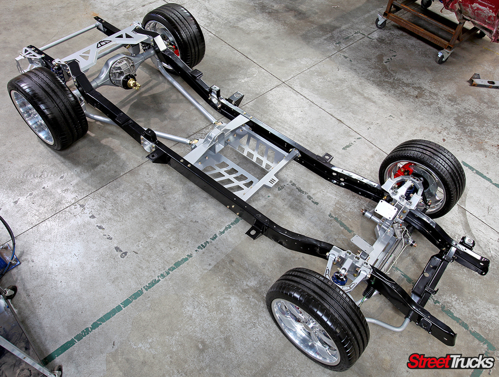
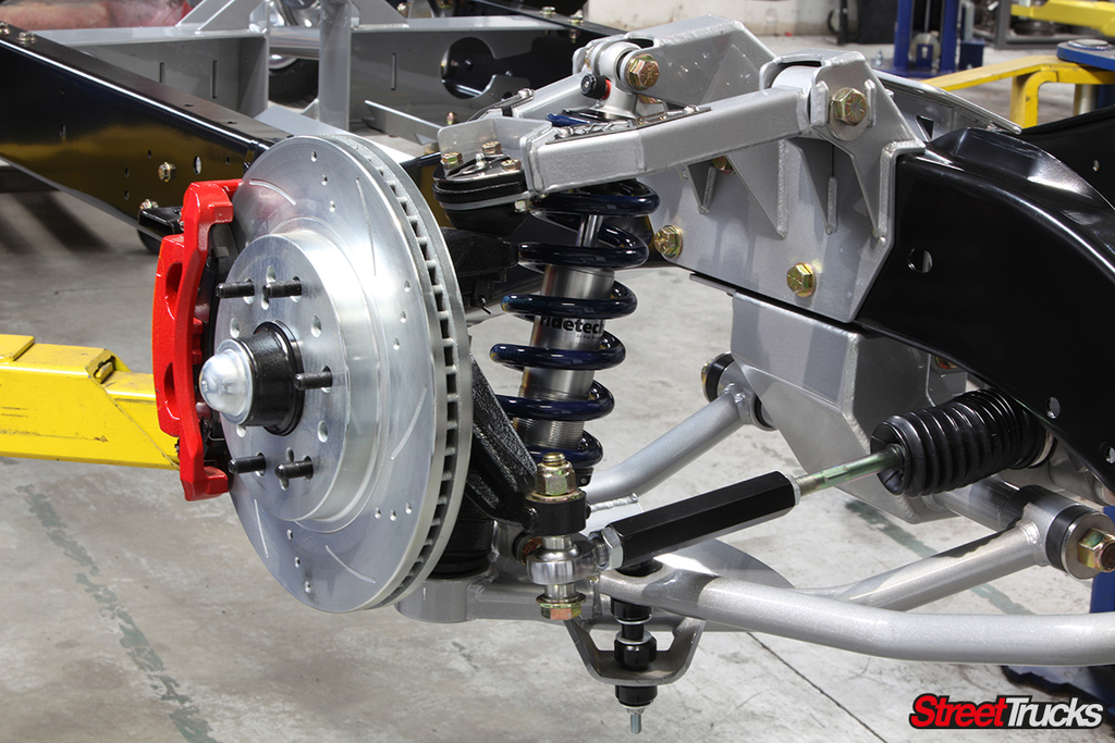
This finished version shows how the whole system looks after final assembly with the 13-inch cross-drilled and slotted brake option. The tie-rod adapter was included with the kit and not shown in the installation. The sway bar is an optional piece.
Chris Hamilton is an automotive journalist, editor, and lifelong truck enthusiast with extensive experience covering custom truck builds, fabrication, performance upgrades, aftermarket products, and a ...
We use cookies to enhance your browsing experience, serve personalized ads or content, and analyze our traffic. By clicking "Accept All", you consent to our use of cookies. Visit our Cookie Policy for more info.


Share Link