FRONT SUSPENSION AIRBAG AND CONTROL ARM UPGRADES TO THE ’70 C-10
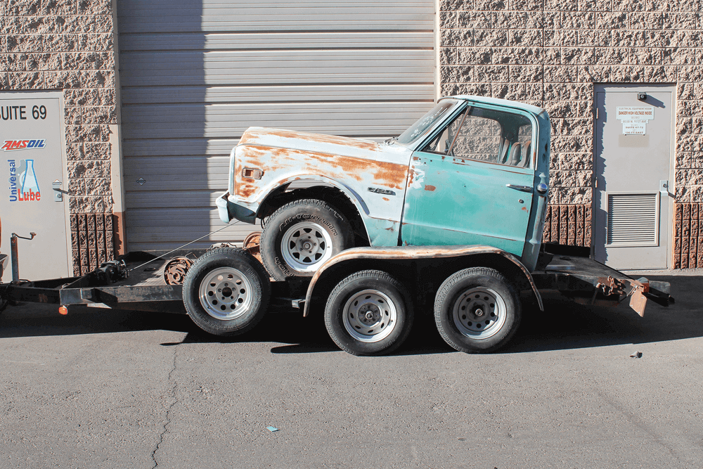
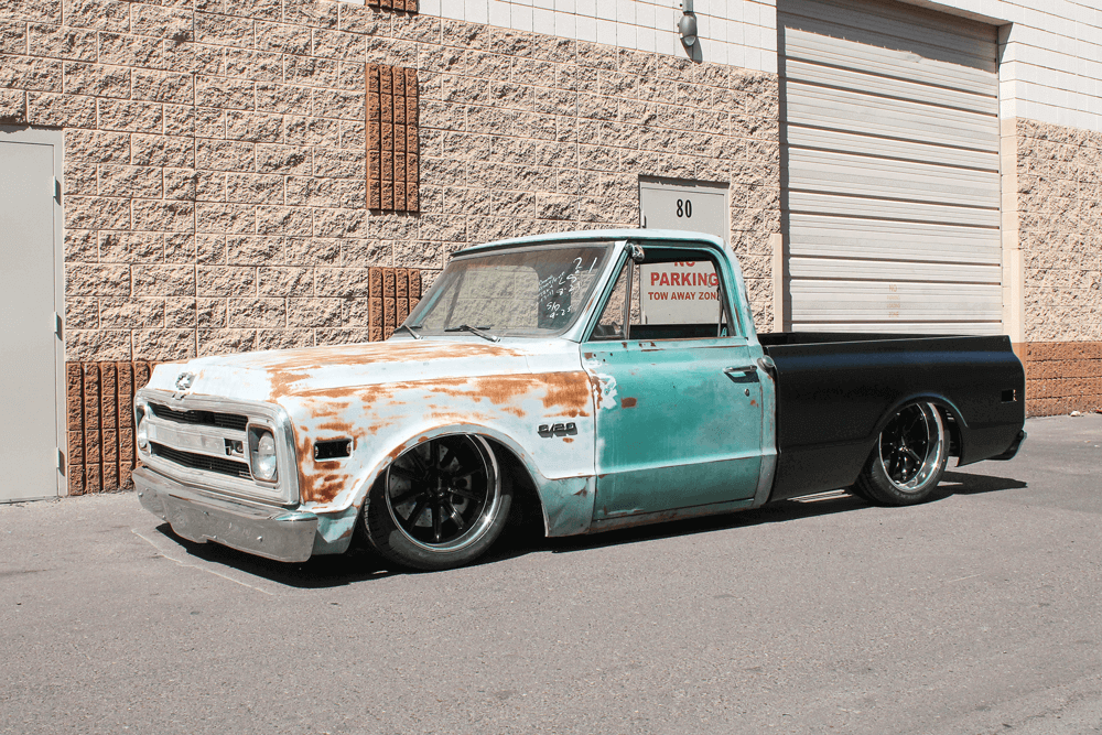
IN THE FIRST installment of the build-up of our new project truck, a ’70 Chevrolet C-10, we tackled the rear frame section and rear suspension (“Built, not Bought,” Sept. 2018, pg. 108). But, let’s take a minute to refresh your memory. We picked up this beauty of a project from someone’s backyard because the metal was in great shape. Along the way, the previous owner had chopped off the rear portion of the frame and the bed was totally gone. After installing the new rear frame section and rear suspension, we focused our attention on the front end of this C-10 that would soon be a driver. The rear suspension kit we already installed is meant to set the truck very low to the ground and is adjustable via air springs. Since the rear of the truck is on ’bags, we also needed to look for a way to get the front of the truck closer to the ground with the adjustability of air suspension.
The great thing about the popularity of C-10 trucks is that there are plenty of resources for aftermarket suspension parts. We knew that we didn’t want to go as far as replacing the entire front cross member, so we looked for our best option in the form of a control arm kit. Since we have worked with Michigan Metal Works (MMW) in the past, we reached out to the company for help getting the truck’s front end as close to the ground as the rear already was.
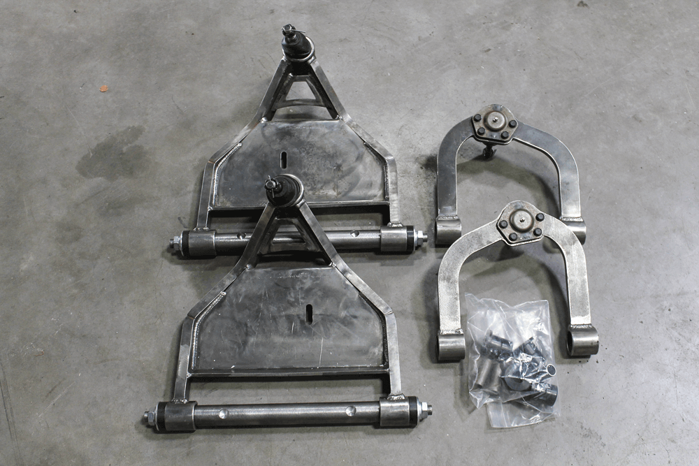
Taylor over at MMW suggested a complete control arm kit in the fl at plate design. The kit comes with all of the parts necessary to remove the factory control arms and replace them with MMW versions. The benefit of replacing the control arms when ’bagging the front is that everything just bolts right in. There’s no need to cup the factory lower control arm or re-angle the upper ball joint for travel. The kit also narrows the track width of the truck and centers the wheel in the wheel well, which are important details.
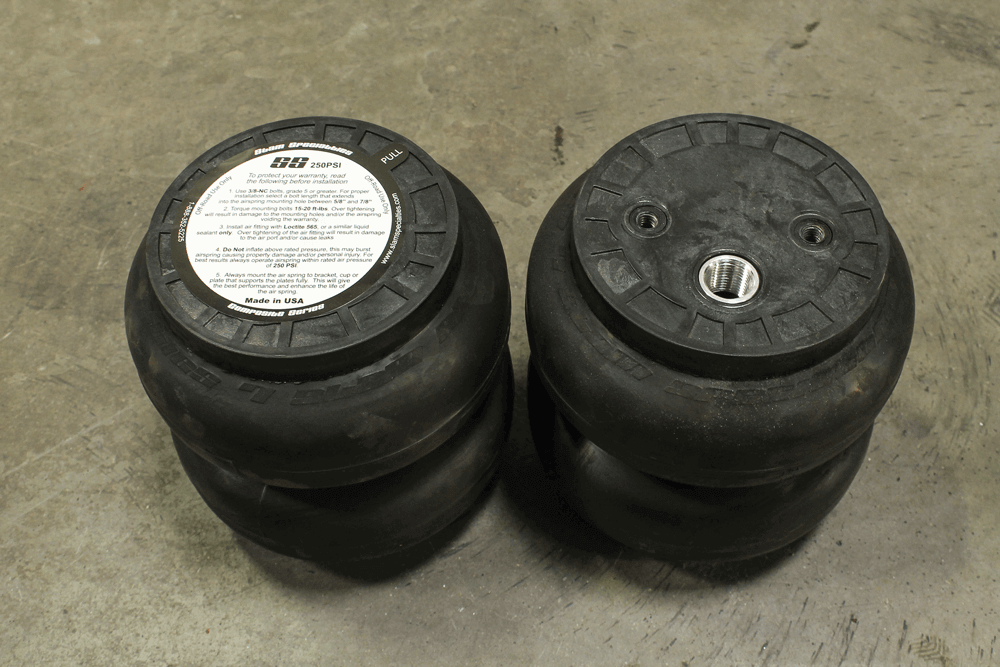
Along with the new control arm kit, we also needed to source a few extra parts. Since the MMW kit is designed to be used with a double convoluted-style ’bag, we ordered a pair of Slam Specialties SS7 airbags to hold the weight of the truck and give us the adjustability we would need. We opted for these ’bags because they are rated for 250 psi and are the correct diameter for the C-10 suspension. The major benefit of the Slam SS7 is that it does not increase in diameter when inflated.
Rounding out the parts necessary for the installation were a pair of shocks we sourced from our local parts supplier and some bolt-in ’bag mounts that we built in-house on our CNC plasma table.
Follow along as we turn this rock into a roller, and stay tuned for the next step.
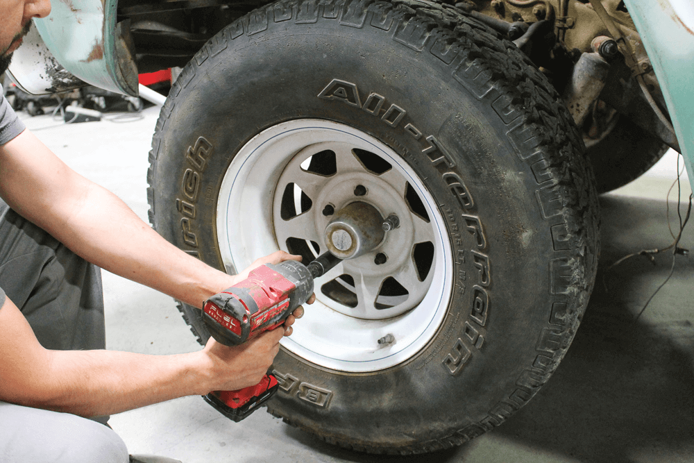
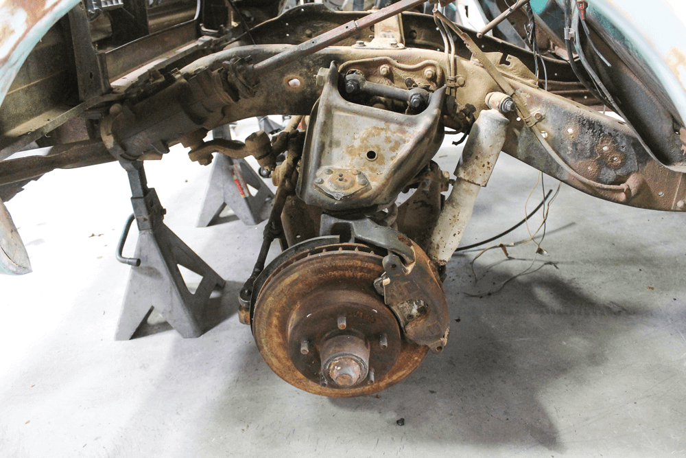
In case you missed the first article, here’s how the truck showed up to our shop. It was obviously missing the entire rearend, but we knew we could handle it.When we did the rear suspension installation, we put the truck on jack stands and leveled it. Our first order of business when we moved up front was to remove the steel wheels.Removing the wheels revealed the nearly 50-year-old front suspension, complete with plenty of rust, grease and road grime.
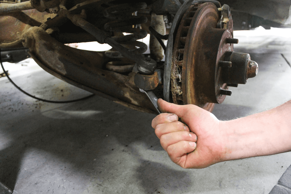
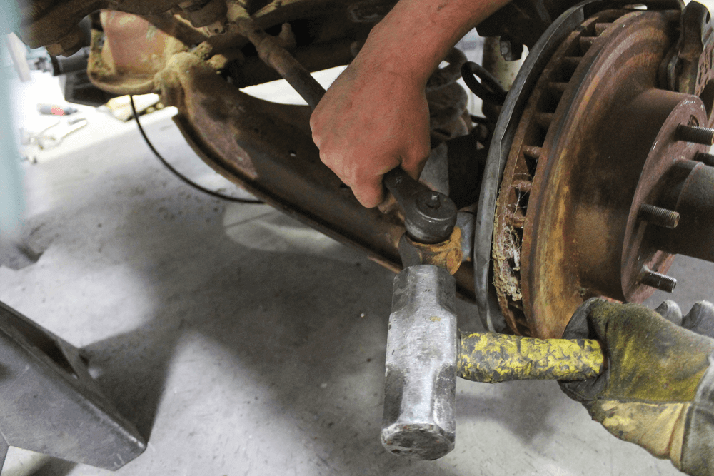
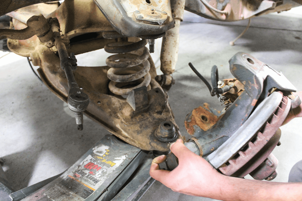
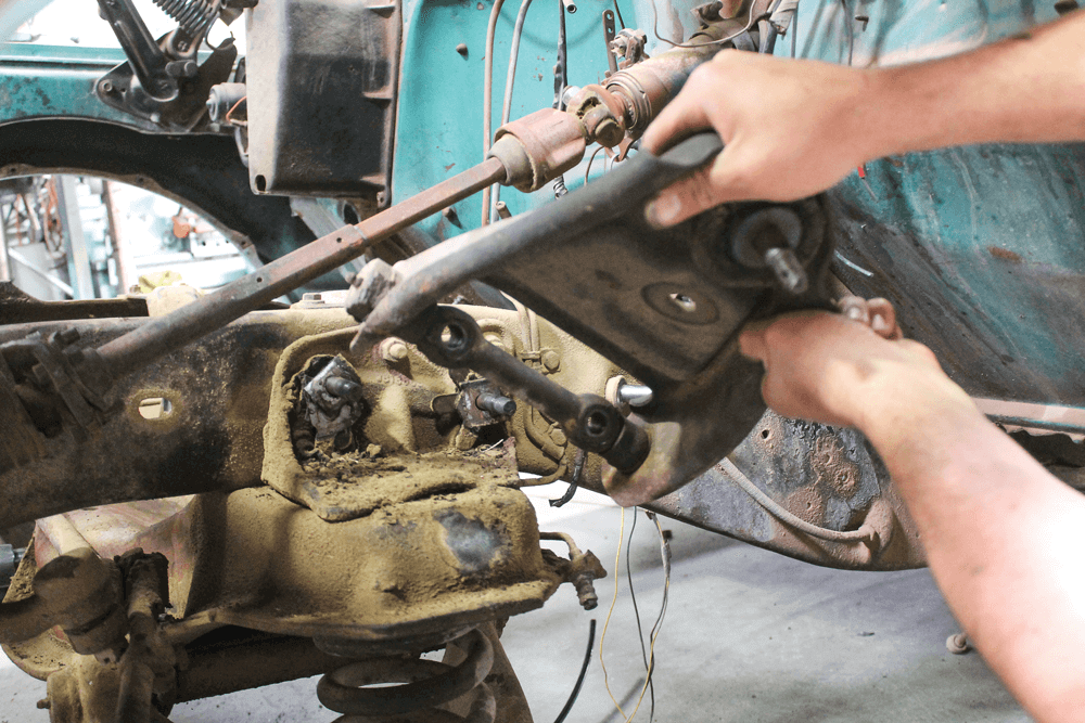
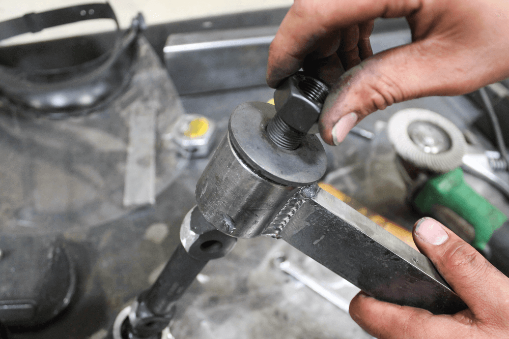
To get rid of all of the nastiness that made up the front suspension, we removed the tie rod end. Doing that first gave us easier access to the ball joint nuts because we could rotate the spindle freely. Since the parts were joined for so long, some extra force, in the form of a pickle fork and a sledgehammer, was needed to free the tie rod end from the spindle.After removing the tie rod, we supported the suspension with the floor jack and began removing the ball joint nuts.
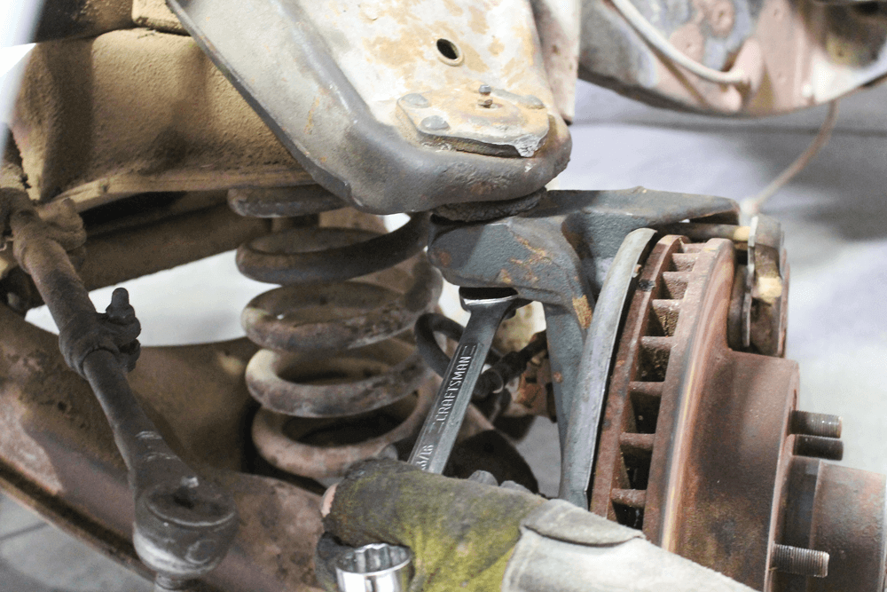
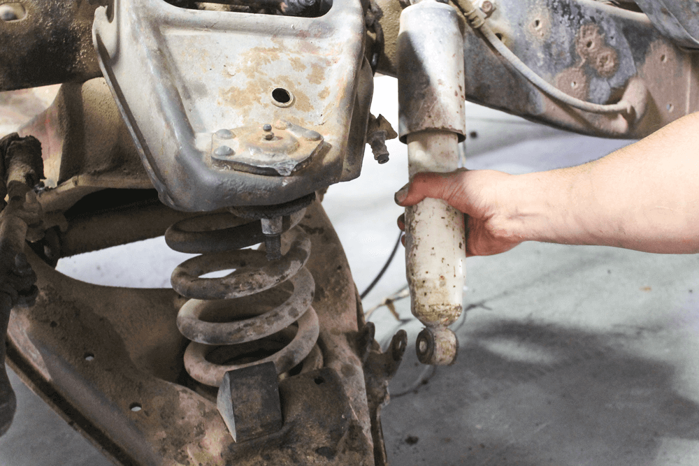
Just like the tie rod ends, these tapered seats were pretty locked in, but we used the same removal method and were able to free them from the spindle. The floor jack under the lower control arm is very important because the coil spring is under a lot of tension. Bad things can happen if you don’t follow this procedure.After removing the spindle, the shock was up next. We won’t be using these any longer, so we tossed them on the scrap pile.
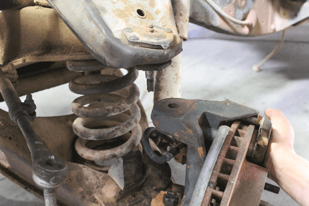
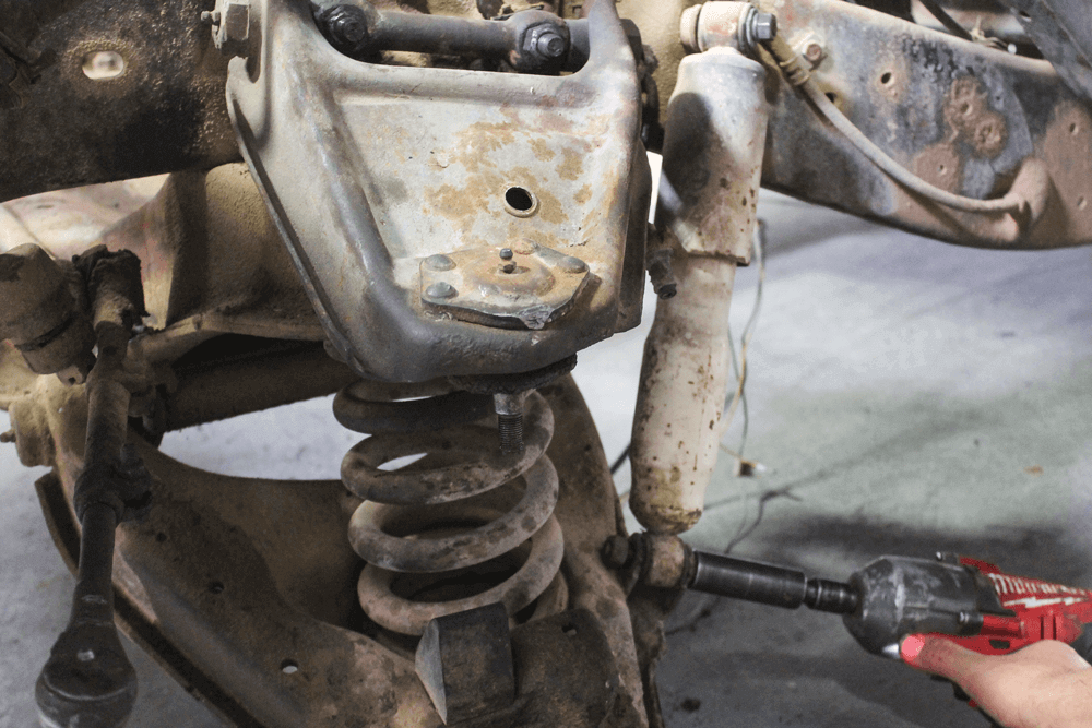
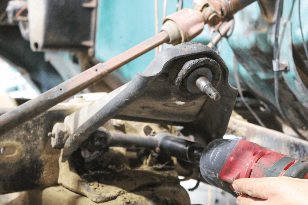
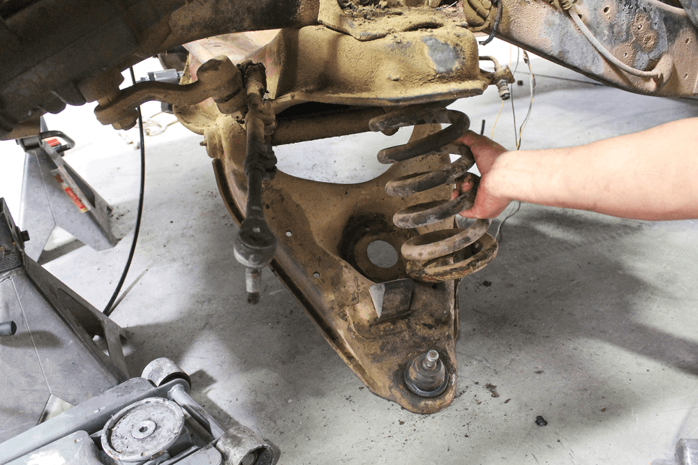
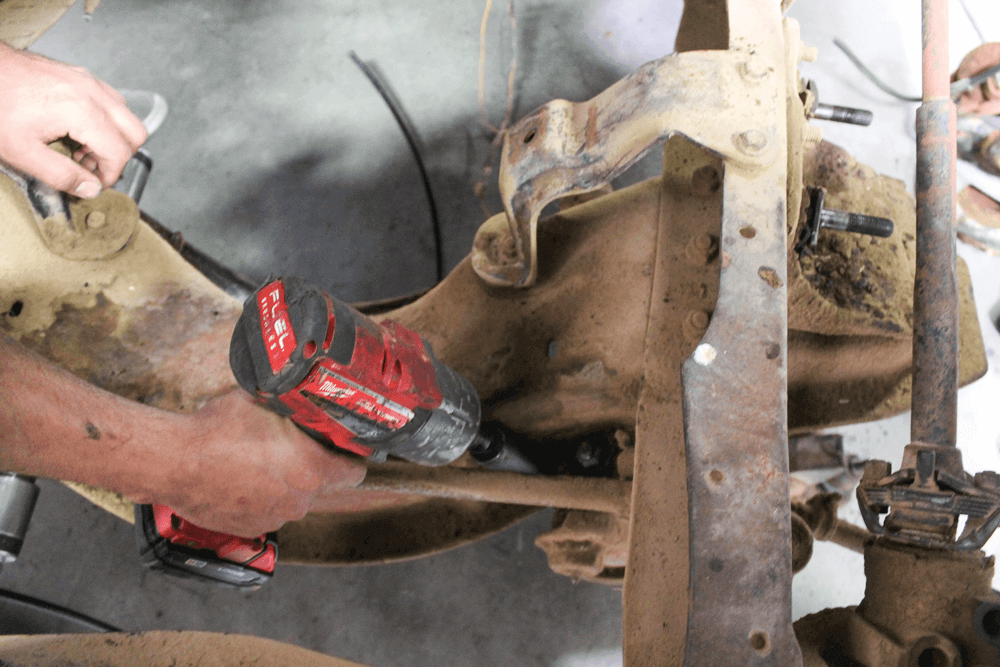
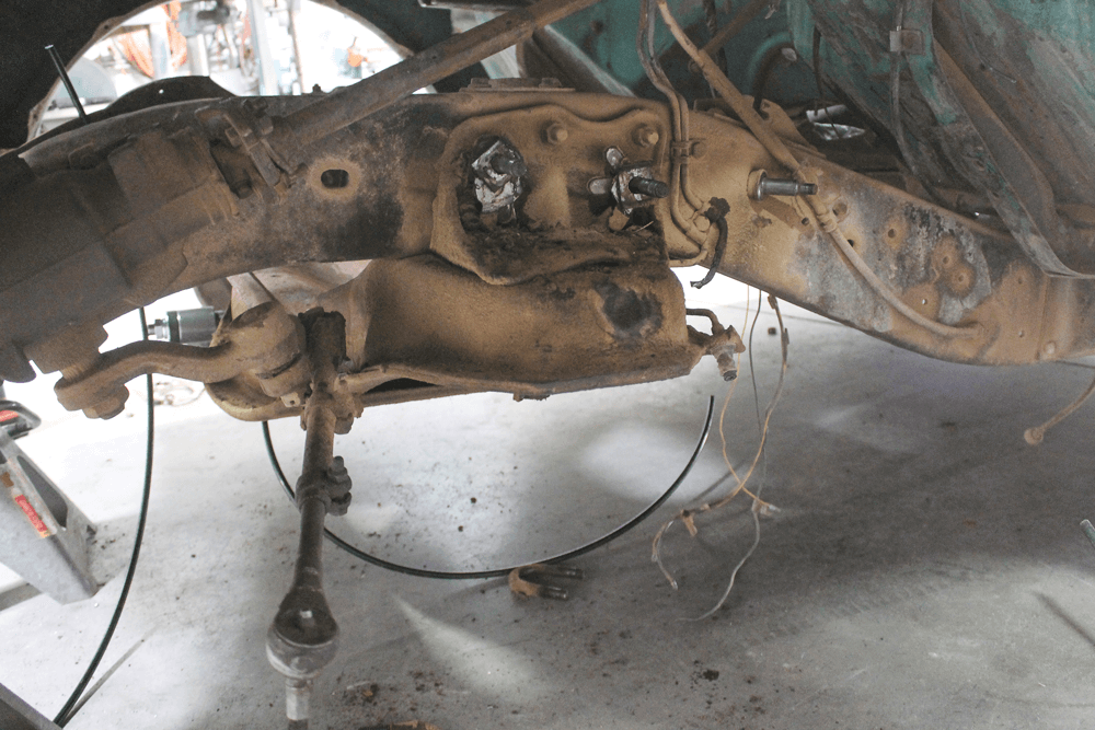
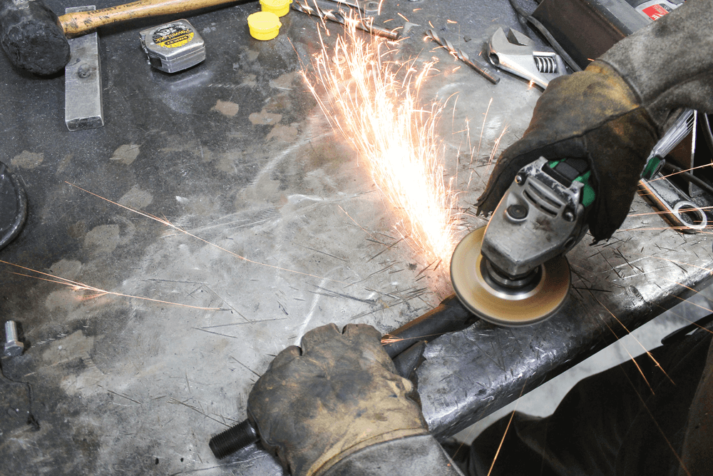
The upper control arm is attached to studs that are pressed into the upper control arm mount. An electric impact made quick work of removing the nuts.There were a few shims on the studs of the upper control arm. These are what the alignment shop uses to correct the amount of camber and caster in the suspension. We made sure to hang on to them for use when we need to get the truck aligned.With most of the factory suspension removed, we were able to lower the jack and allow the coil spring to drop out of the coil bucket. Since we intended to convert to airbags, the stock coil spring found its way to the scrap pile as well.We did get pretty lucky, in some respects, when picking up this truck. Because the engine had already been removed, it was much easier to access the hardware for the lower control arm through the shaft.
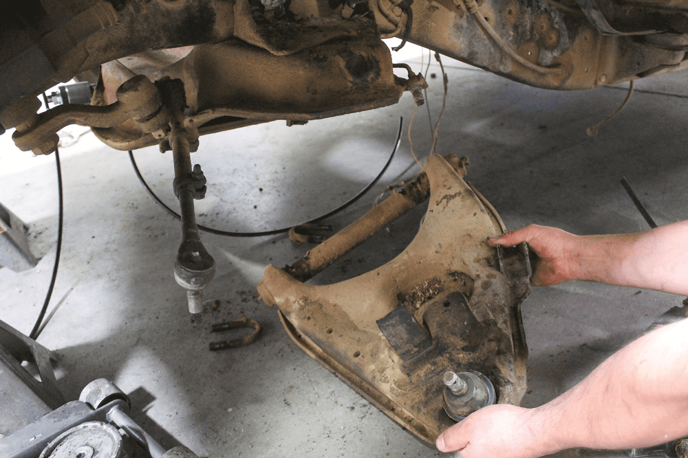
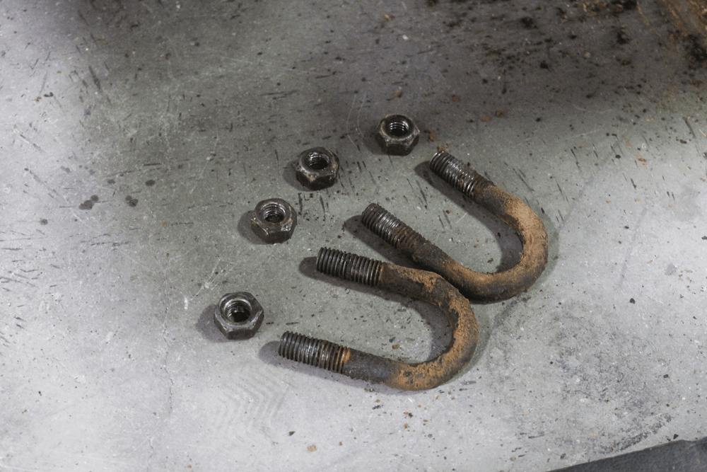
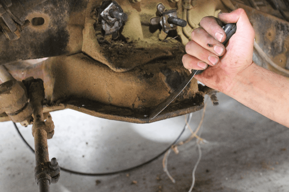
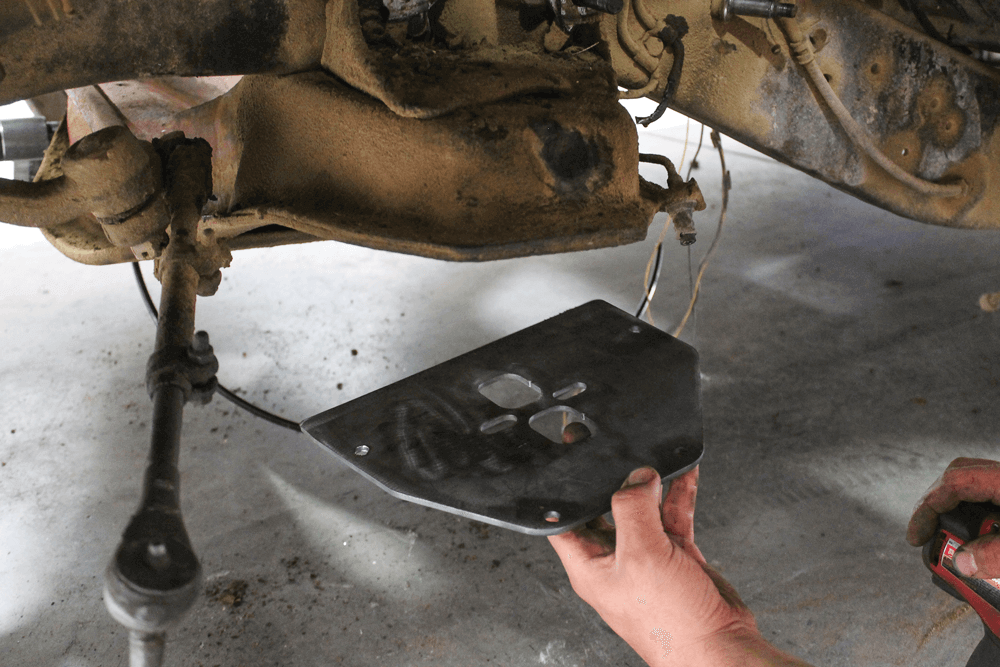
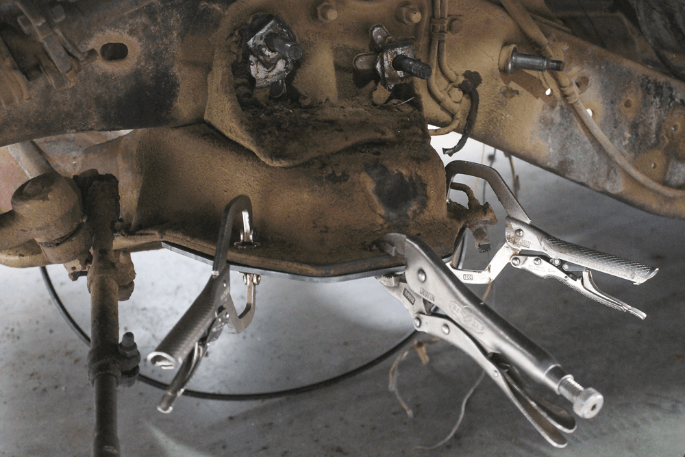
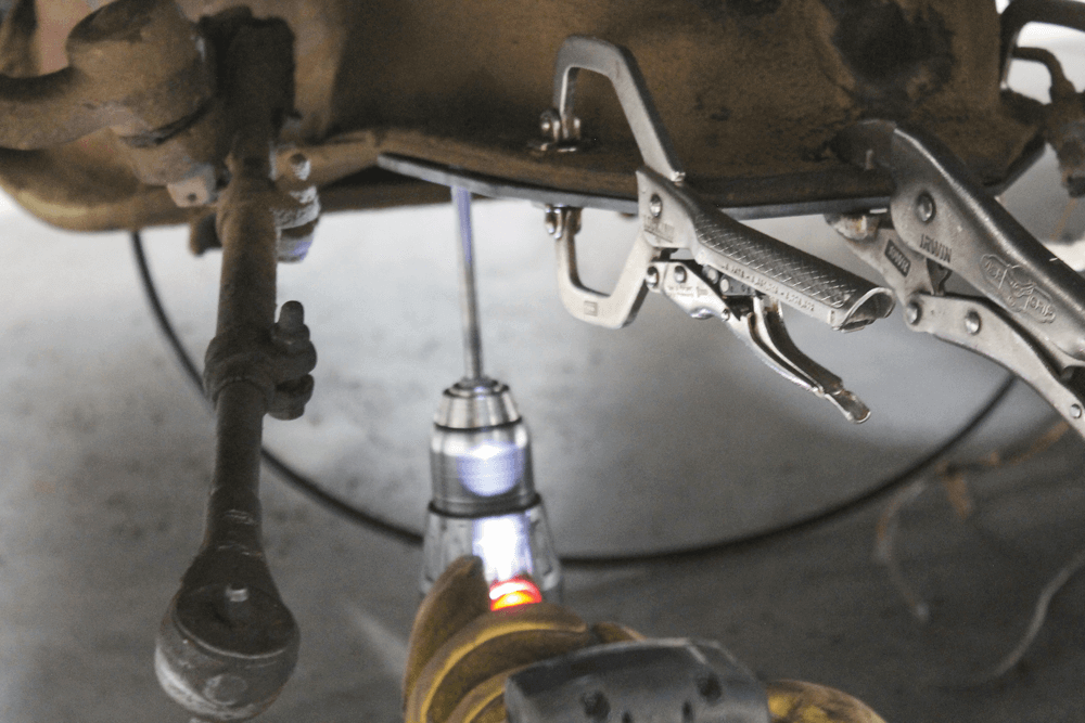
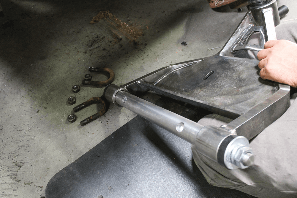
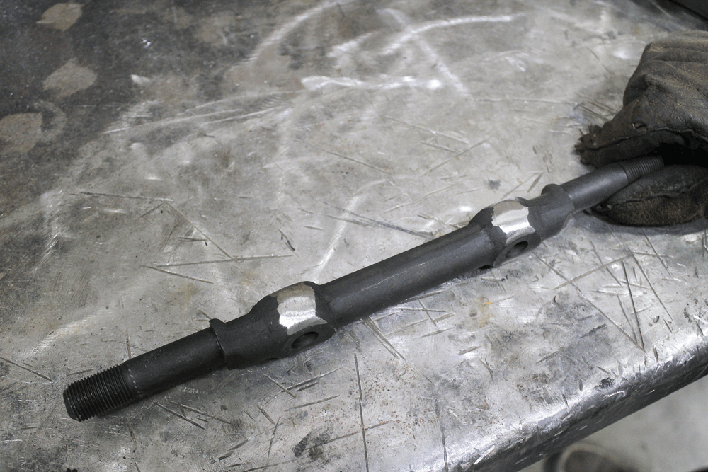
Once we removed the nuts securing the U-bolts, we tossed out the lower control arm. This step is still totally doable with the engine in the truck, but there’s much more room when it’s out of the way.After about an hour spent fighting the old hardware and ball joints, we were left with a bare front frame section.Most people would take this opportunity to clean up the frame rails and cross member, and maybe spray on a coat of paint. We planned to completely tear the truck down for powder coat after we were finished mocking-up everything, so the only area we needed to clean up was where debris collected around the upper hat.Luckily for us, we had a CAD file for the upper mount because we intended to bolt the new upper ’bag mount through the lip. We whipped out a couple on the CNC plasma and began to install them.We used C-clamps to hold the plate in place so we could mark it for a few bolt holes.Before we removed the plate, we actually used the drill to mark the holes since the marker doesn’t show up very well on greasy metal. Then we removed the plate and drilled the holes.Next, we started installing the new MMW control arm kit. This photo shows everything included with the kit: upper and lower control arms, upper and lower ball joints, and the lower cross shaft. The only other part needed was a new upper cross shaft, which we purchased from a local parts supplier.Installing the new lower control arm was done in the reverse method of removing the factory arm. The new MMW cross shafts have the same reliefs machined into them as factory.
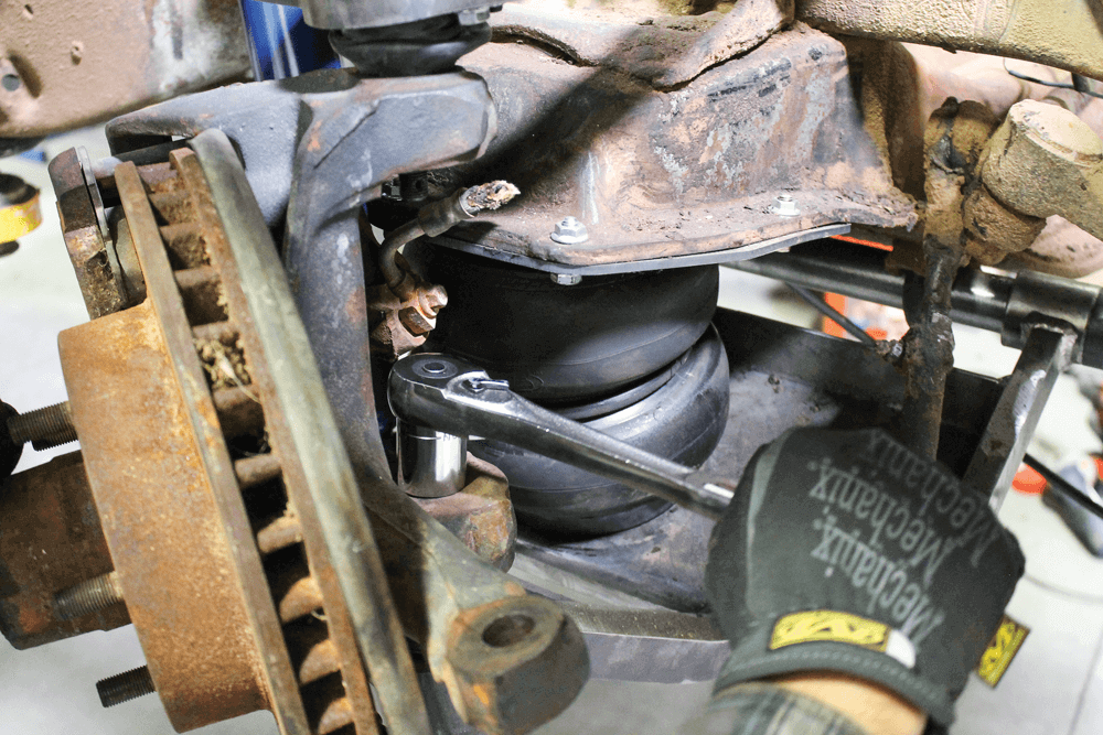
We reused the factory U-bolts and hardware to install the new arm. After aligning the reliefs to the cross member, we tightened the U-bolts.The MMW arms are designed to be used with a double convoluted-style airbag. These Slam Specialties SS7 airbags fit the bill.
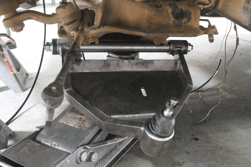
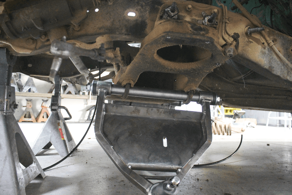
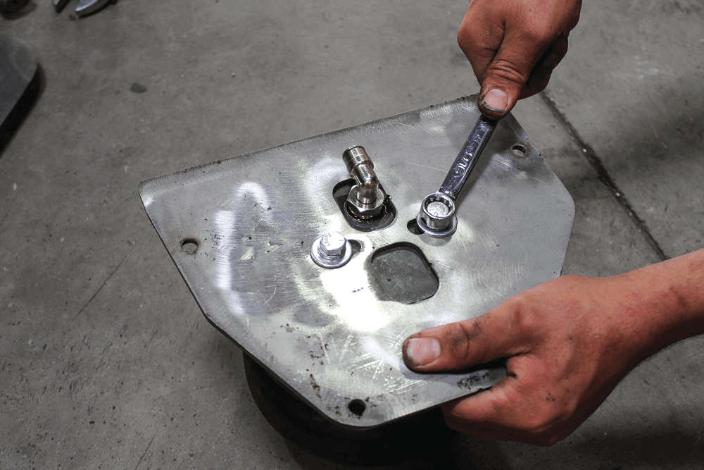
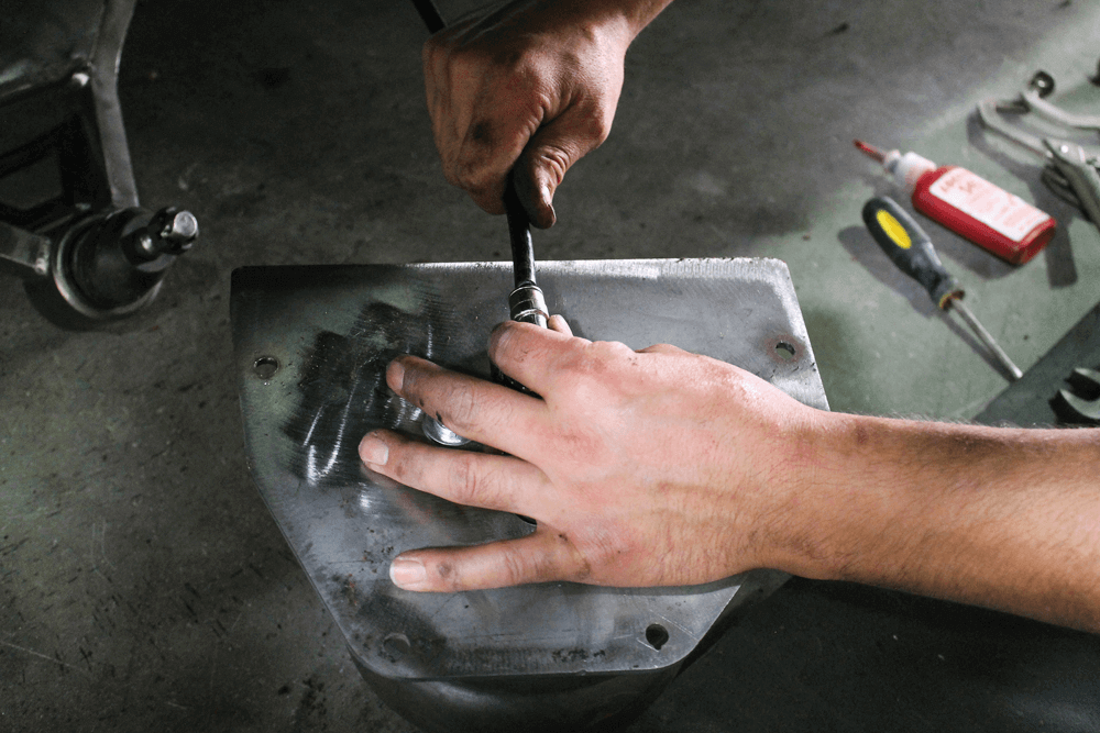
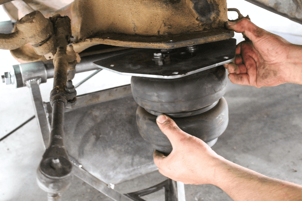
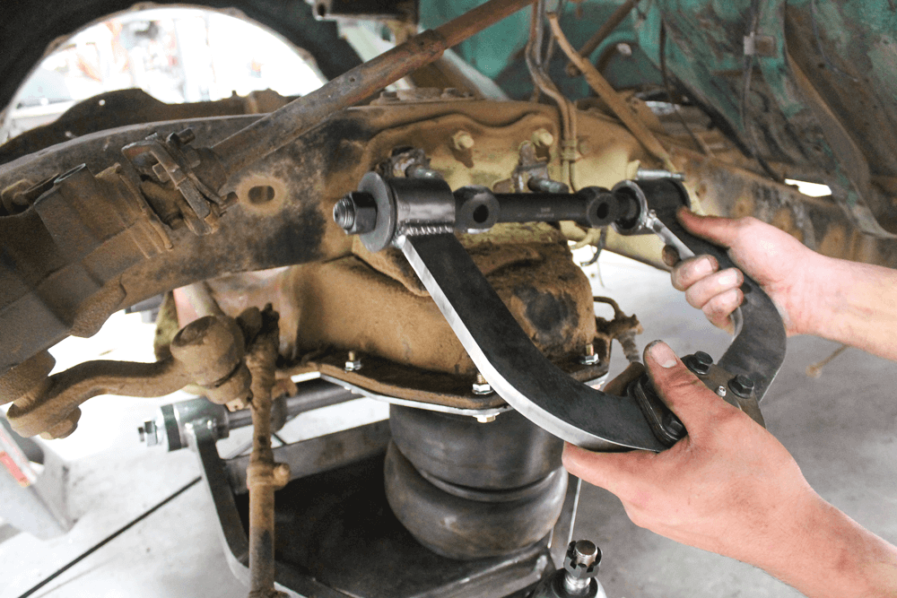
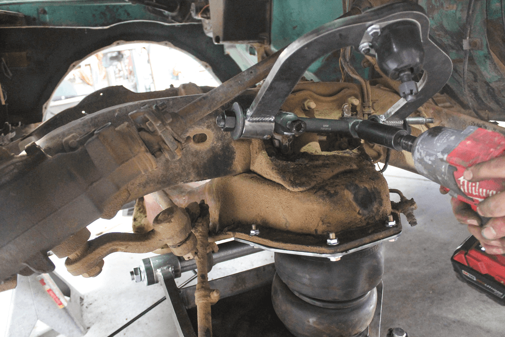
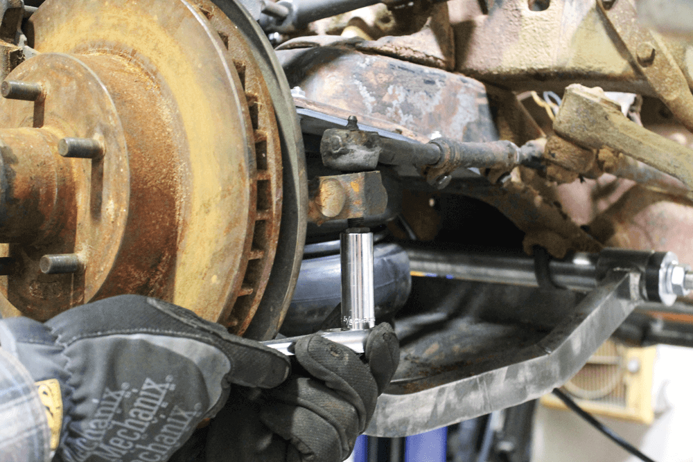
Because the fitting and air line will be completely hidden in the cross member, it was necessary to install the ’bag onto the plate and install the fitting and air line before mounting it to the truck.With the air line securely connected to the fitting on the ’bag, we fished the line through the cross member and positioned the ’bag plate against the cross member.Then we used new hardware to mount the assembly to the truck.
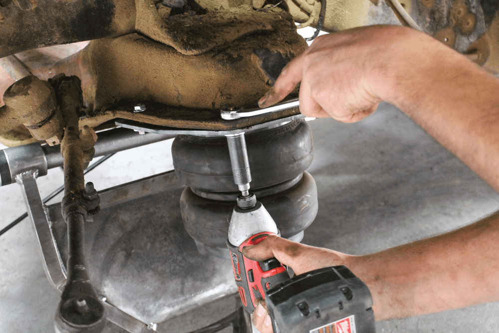
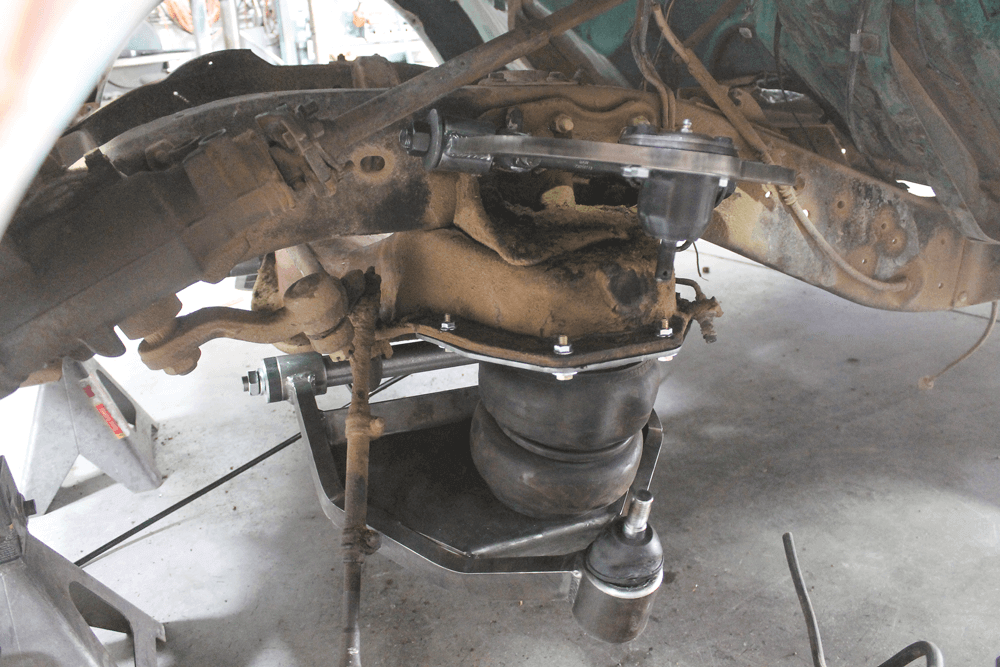
After tightening the upper plate, we swung the new lower control arm up to the ‘bag and installed the bolt from below the control arm and into the bottom of the ’bag.
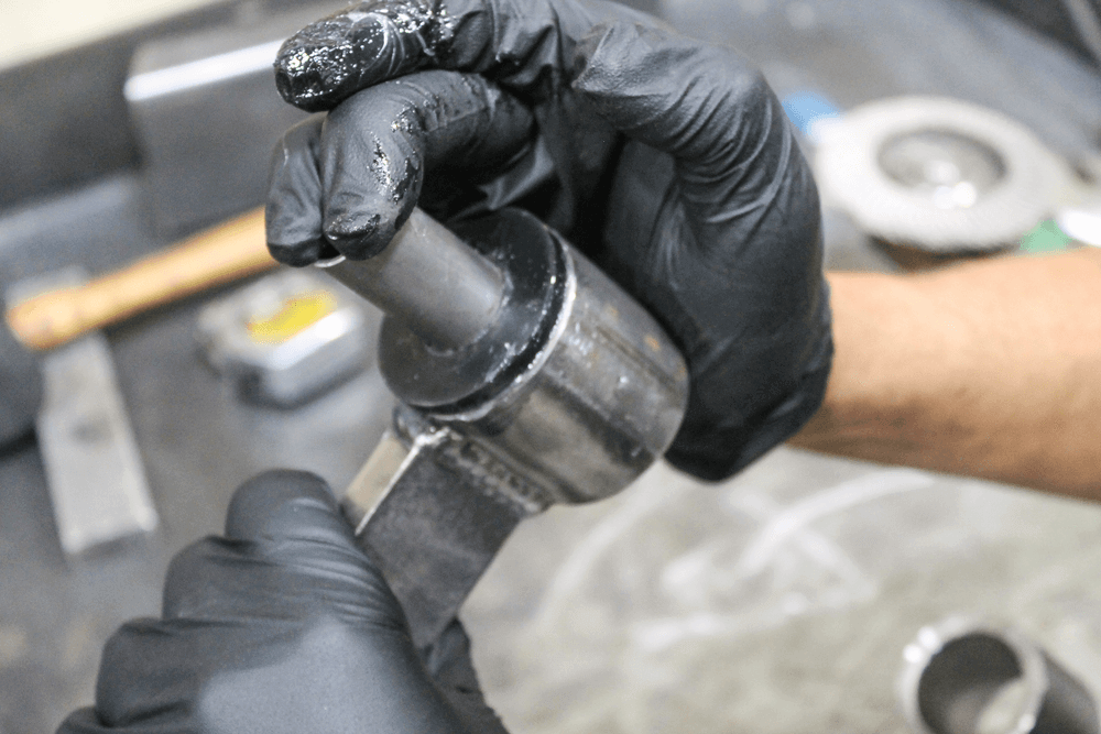
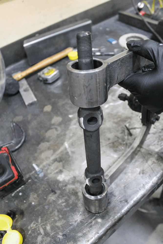
The upper control arms do not come with new upper shafts because the stock-style versions can be reused. In our case, we just decided to buy new ones. They are a stockreplacement- style cross shaft (P/N K6184) we got at our local parts store. Some light sanding was required.To assemble the new upper control arms with the new shaft, a light coating of lubricant was applied to the bushings on one side of the control arm.The cross shaft was slid through the open end of the upper arm.Then the other bushing was slid over the cross shaft and into the opposite end of the control arm. The hardware provided with the new cross shaft was tightened.
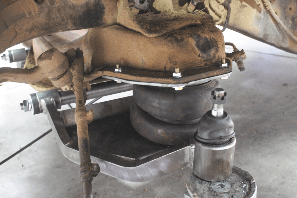
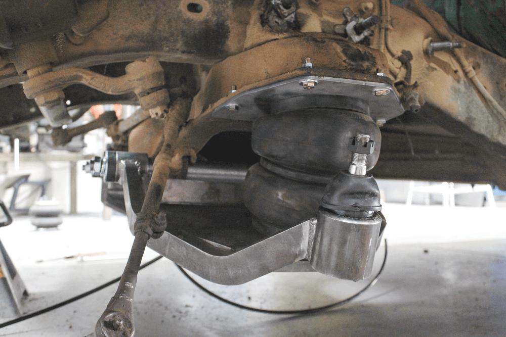
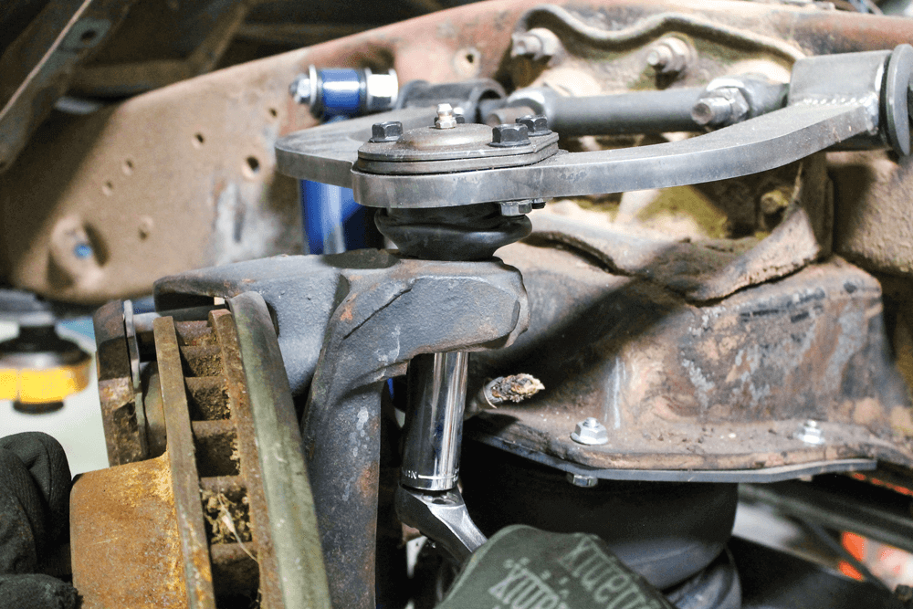
The new upper control arm assembly was slid onto the factory studs on the frame. We put an equal number of shims on the front and rear studs in order to have a good starting point for the alignment shop, once we get to that stage of the build.With the new control arm kit completely installed, we were ready to install the spindle and brake assembly.
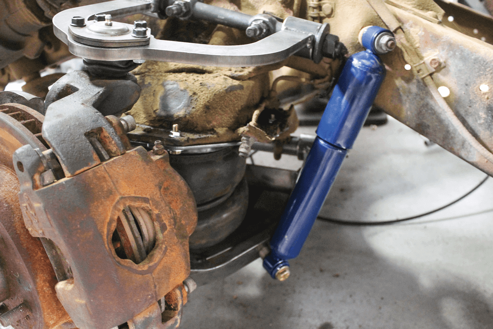
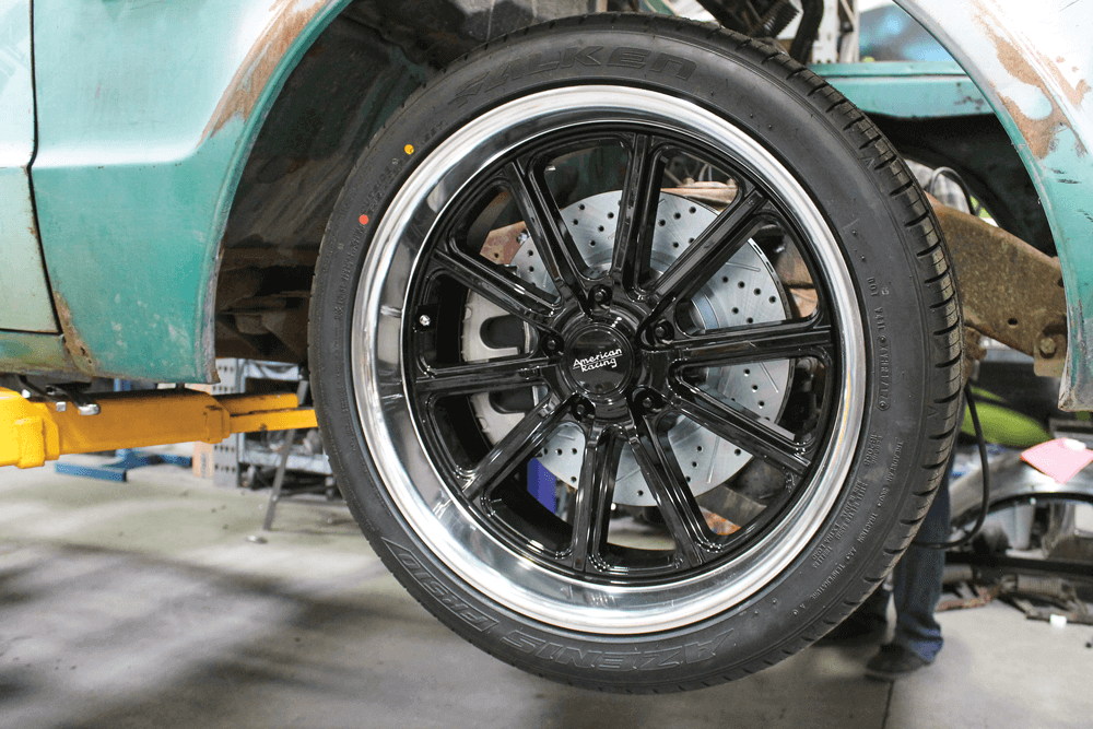
For now, we just reinstalled the factory spindle and brake setup because we have some future brake upgrades planned. Look for that in the next installment of the build.Concluding the installation of our new airbag front suspension was a new pair of shocks. These are nothing fancy, we just figured out the correct length we needed and grabbed some from the parts store.Once we had both sides of the front suspension done, we installed our new rolling attire. These are American Racing’s new VN507 Rodder wheels with a gloss black powder-coated center and a diamond-cut lip. We had the wheels wrapped in Falken Azenis FK510 tires.It took a lot of work to transform this truck from what it was when it rolled into the shop, on two wheels, to what it is now. We still have a lot of work ahead of us, but it sure is nice see it on all four wheels and tires. It’s also nice to be able to roll it out of the shop and let the air out of the ’bags.
We use cookies to enhance your browsing experience, serve personalized ads or content, and analyze our traffic. By clicking "Accept All", you consent to our use of cookies. Visit our Cookie Policy for more info.
 JEREMY RICE
.
August 07, 2023
.
Features
.
JEREMY RICE
.
August 07, 2023
.
Features
.


Share Link