 ST-STAFF
.
January 28, 2019
.
C10 Builders Guide
.
ST-STAFF
.
January 28, 2019
.
C10 Builders Guide
.
TODAY’S BUILDERS demand a lot for their trucks, and this goes especially for the power segment. Getting performance has been more attainable in the last few years and has increased our expectations. There is a huge selection of crate engines on the market, and stout salvaged versions are plentiful.


With great power comes the question of sticking it to the ground, since your truck is only as good as its weakest link. For most that point is the rearend. Fortunately, C-10s have decent versions that can be modified to suit modern demands.
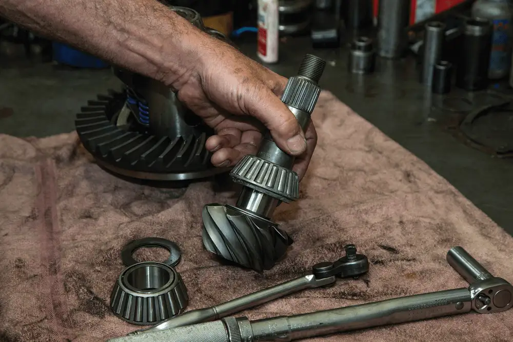
Chances are your truck has a 12-bolt rearend, but if not, it’s fairly easy to get your hands on one. Not only are they common, but they can also be pretty solid when built correctly. In fact, they can stand up to around 800 hp, which is perfect for a street truck with some performance mods under the hood. Thirty-spline axles and a large ring gear help these rearends hold power. They also require less power to turn because of the height where the pinion gear contacts the ring gear.
Since they’re plentiful, a 12-bolt can be found for only a few hundred bucks, but it’s still important to make sure you’re getting one that’s in good condition. While you’re modifying them to fit your needs, you might as well change some of the internals while you’re at it, including the bearings, seals and even the gears.
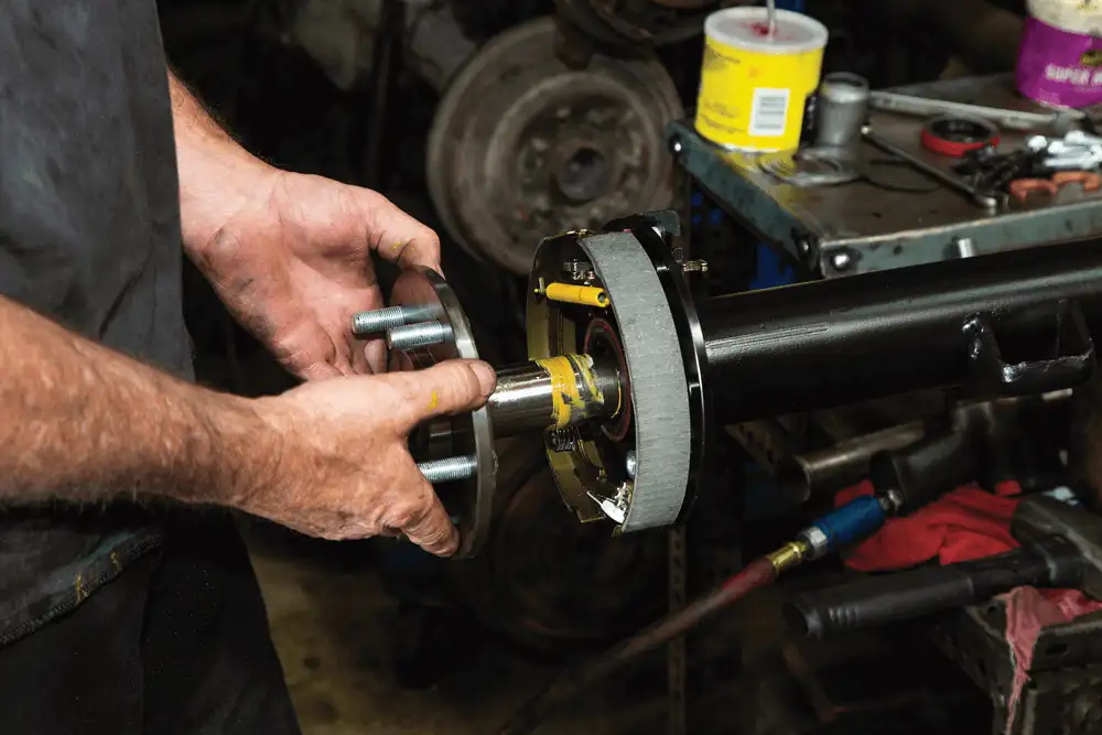
We had a 12-bolt and decided to do a full rebuild. Not only did we want to make it solid, we also wanted to change a few things. We searched Summit Racing’s website to find all of the Yukon Gear and Axle components we needed. We started with 31.5-inch axles (P/N YA G14071751) to convert from a 6- to 5×5- lug pattern. To help our truck jump off the line better, we changed the gears to 4.11:1 (P/N YGA-24130). To make the truck run like new, we ordered a master rebuild kit (P/N YK GM12T).
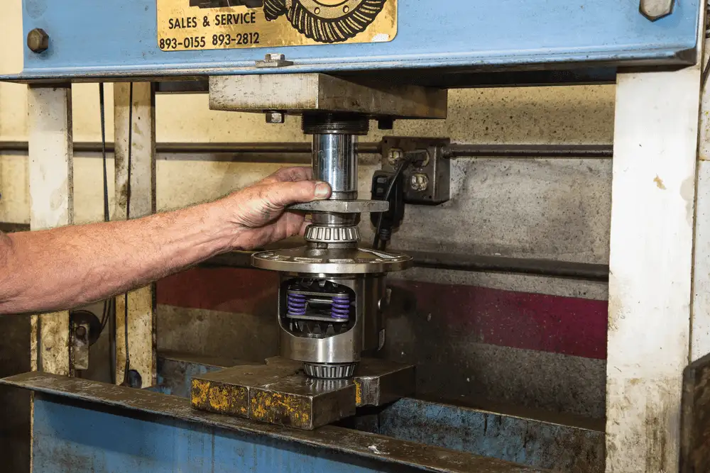
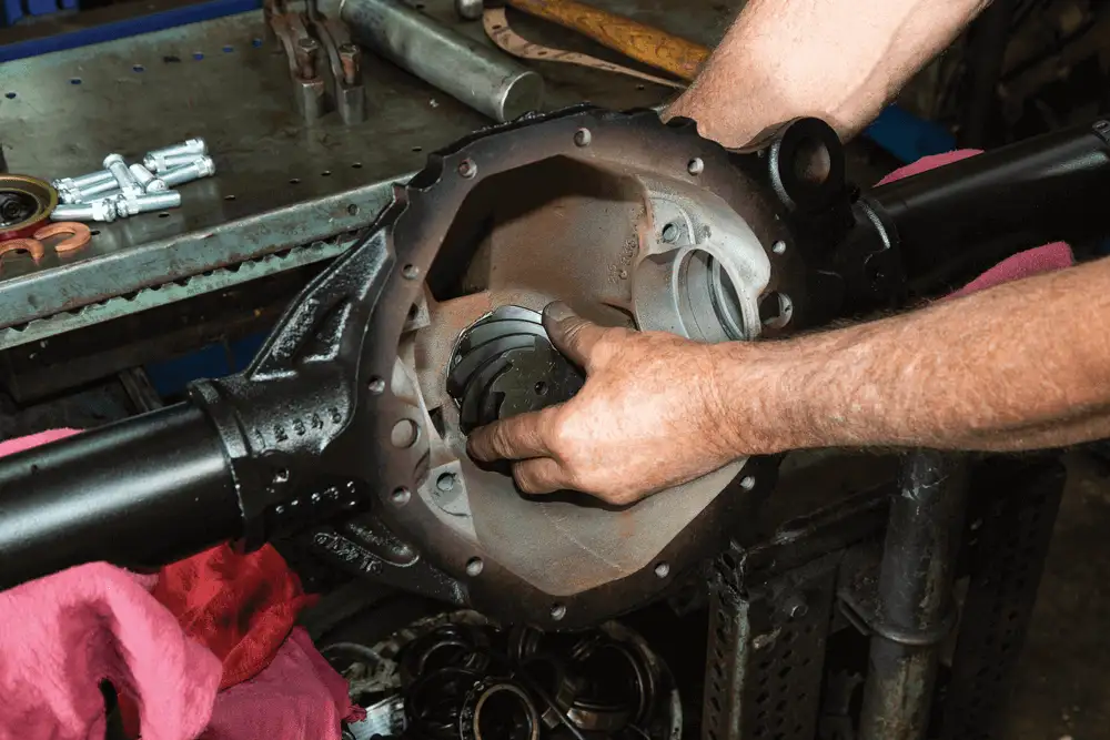
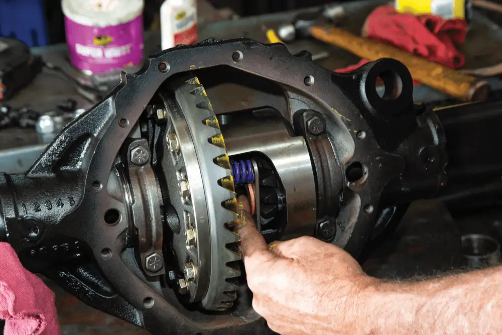
One drawback to running a factory rearend is the open differential. It will allow the wheels to rotate at different speeds for a smooth ride, but it will also transfer power to the wheel that has the least traction. This isn’t ideal when you’re trying to get the maximum amount of power transferred to both rear wheels. To combat this, we ordered a Yukon Dura Grip positraction differential (P/N YDGGM12T-4-30-1), which uses a set of springs to lock two packs of clutches in order to distribute power more evenly between the two separate wheels.
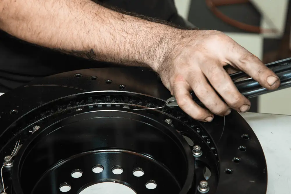
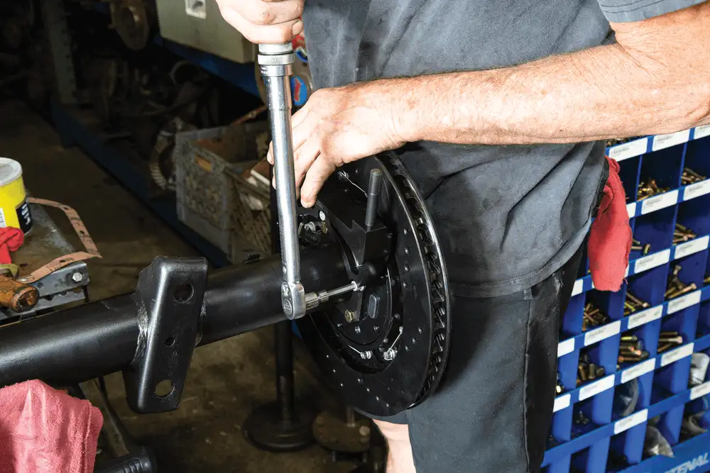
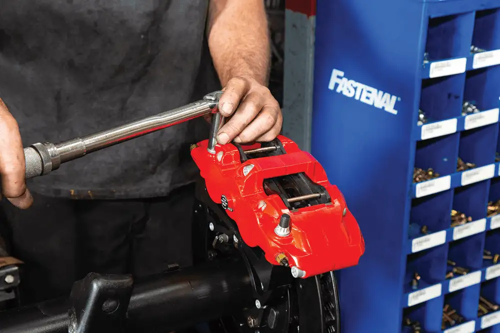
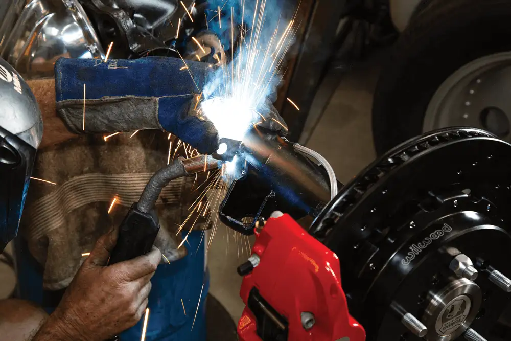
With our rearend set up to help the truck go faster, we thought it would be wise to help it stop shorter too. When it comes to getting better stopping power, Wilwood is at the top of the game. We ordered an Aero6 disc brake kit (P/N 140-15305) for the front with six-piston calipers and 14-inch two-piece rotors. For the rear, we matched it with an Aero4 rear disc/ parking brake kit (P/N 140-10941) with four-piston calipers and 14-inch two-piece rotors.

The included SRP rotors have a drilled and slotted pattern to improve braking response and pad performance. The holes and slots vent and clean to reduce pad glaze and disperse gases and heat. The rear rotor hats also have an internal shoe system that can be used for parking.
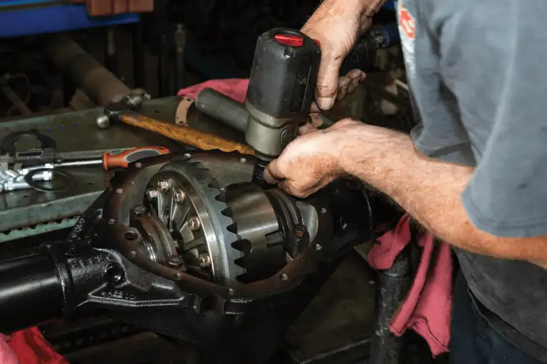
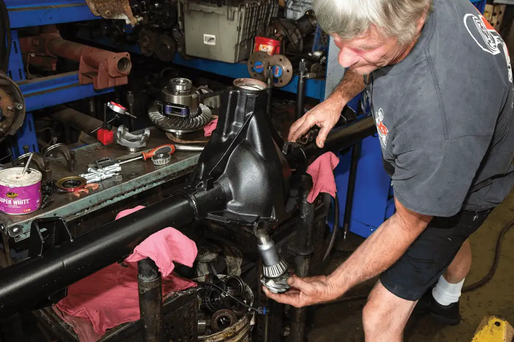
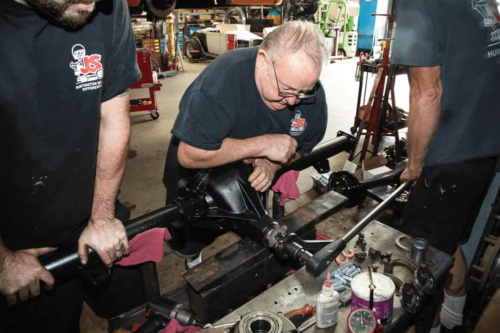
To help us build our rearend, we took everything to J and S Gear in Huntington Beach, California. John Coulman is the man with a plan with more than 30 years of experience building rearends. Not only is he a top-notch rebuilder, he can also narrow rearends to fit specific wheel/tire combos. While talking with John, we discovered that he got into his profession by doing what most of us do: hammering on our vehicles and breaking parts. After watching him build this 12-bolt rearend in just a few hours, we can confirm that he knows his stuff. After a simple rebuild, our rearend was ready to go, moving our project faster and stopping it better.
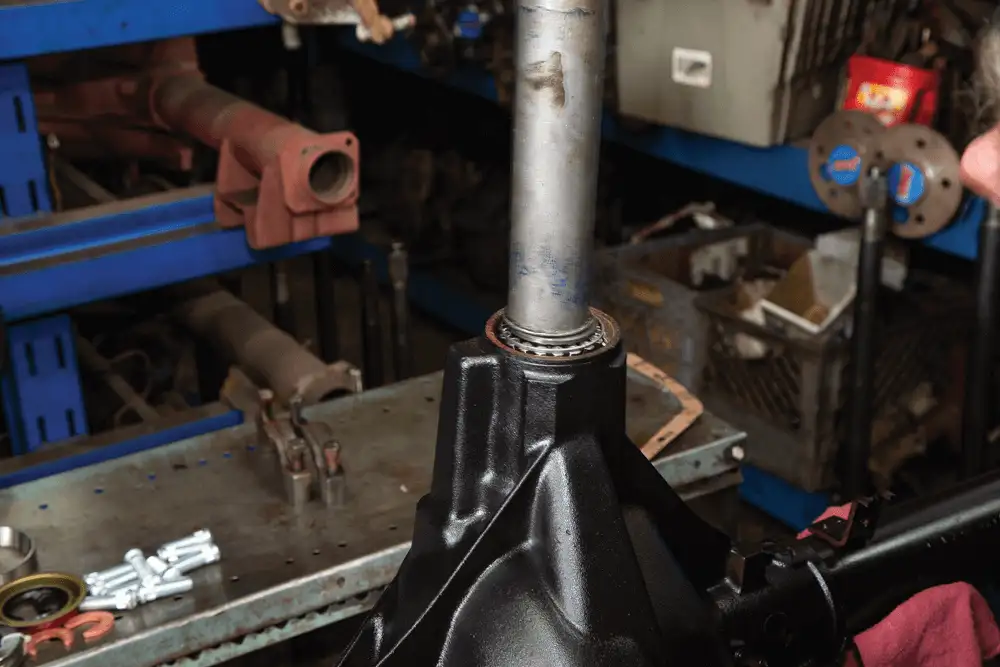
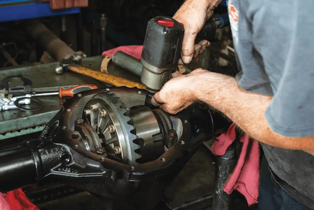
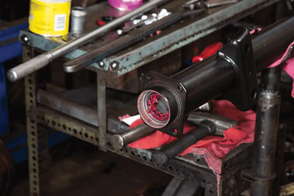
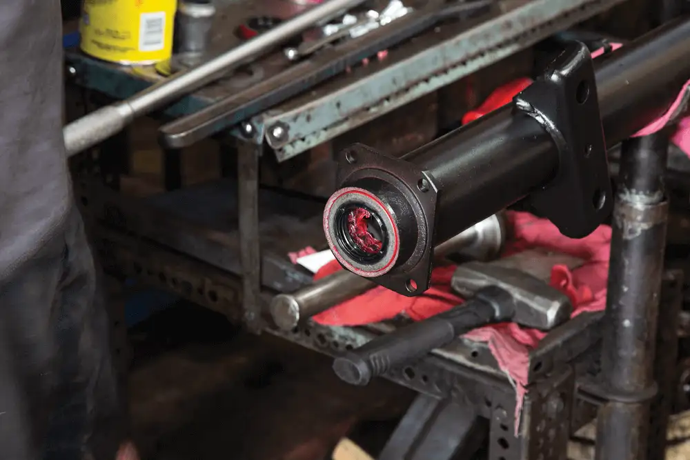
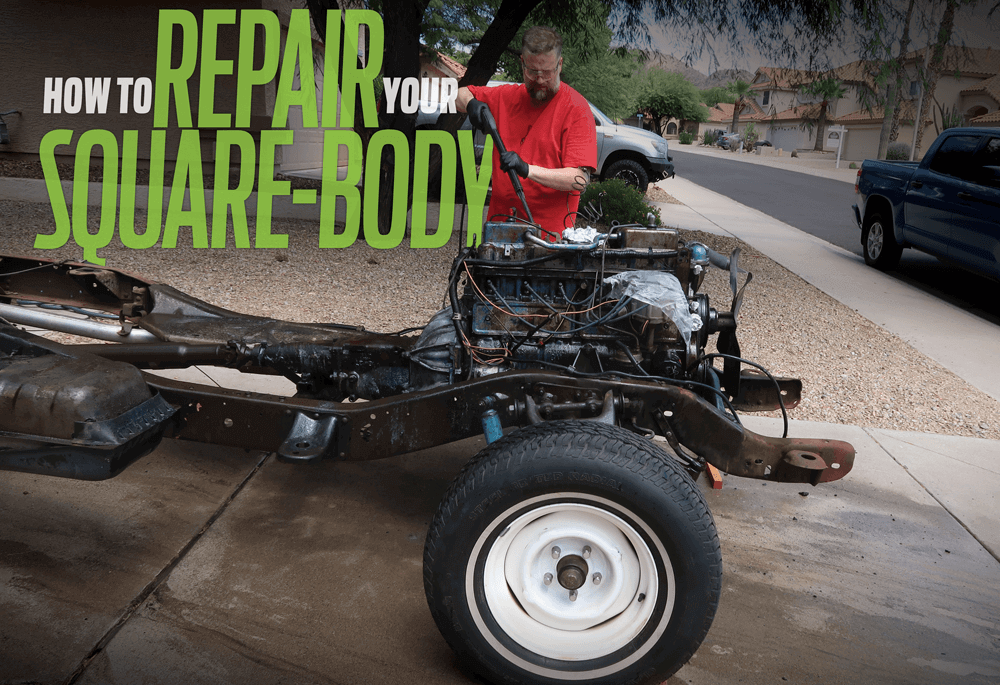
GETTING STARTED
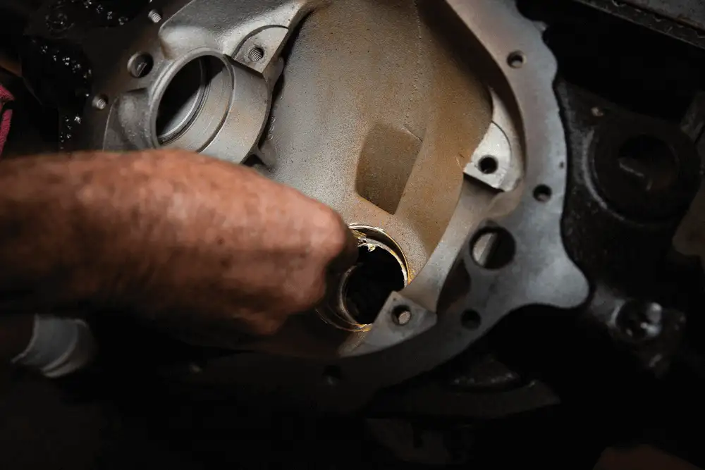
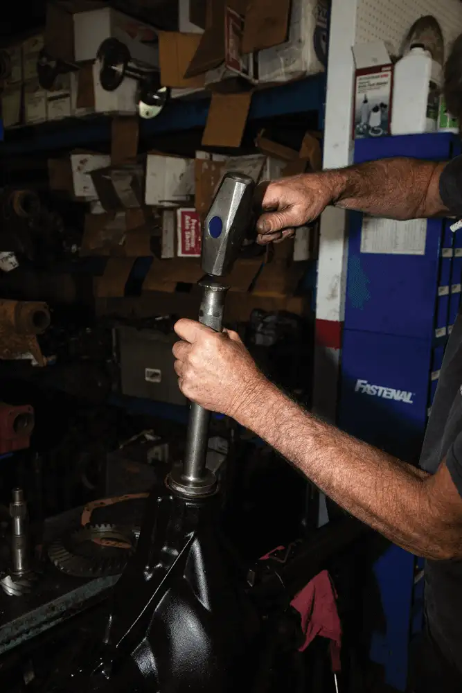
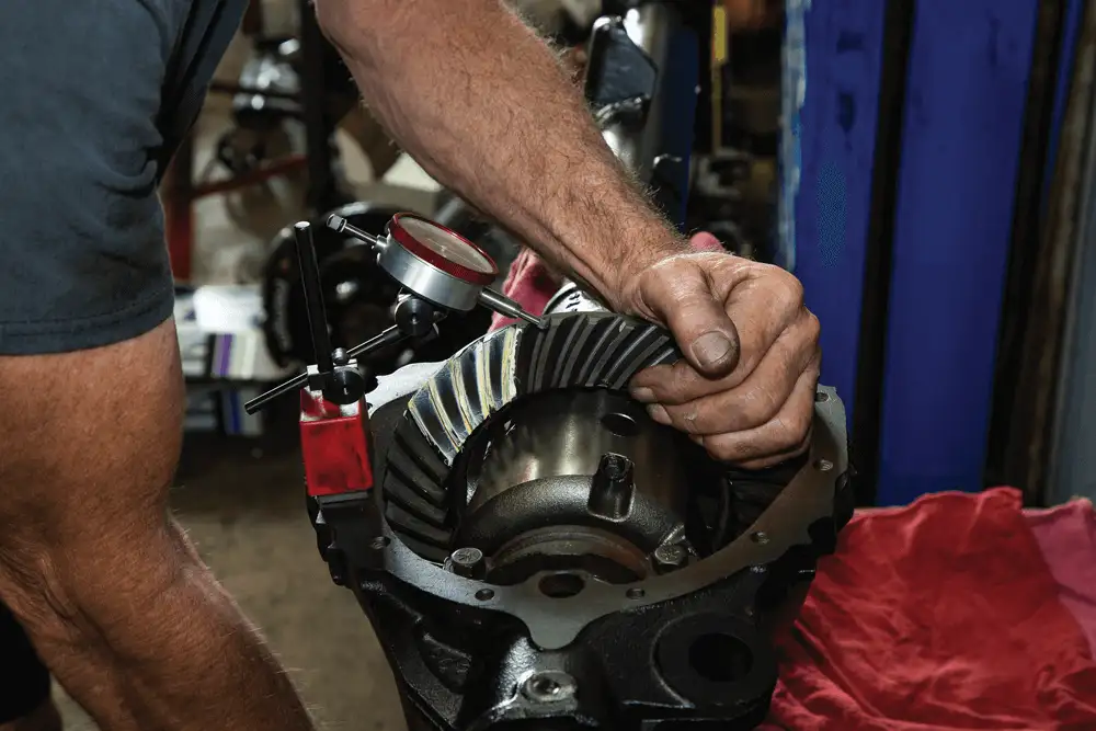
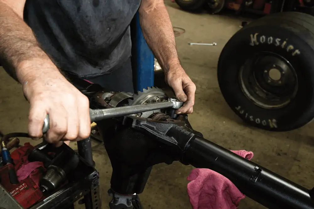
INITIAL SET UP
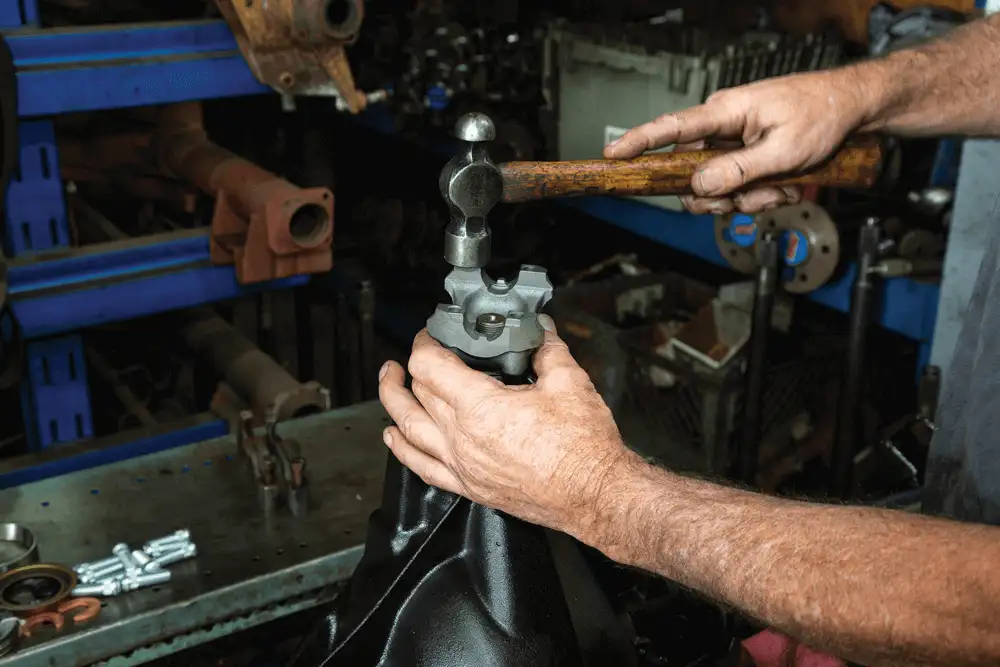
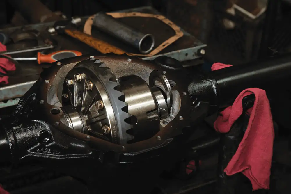
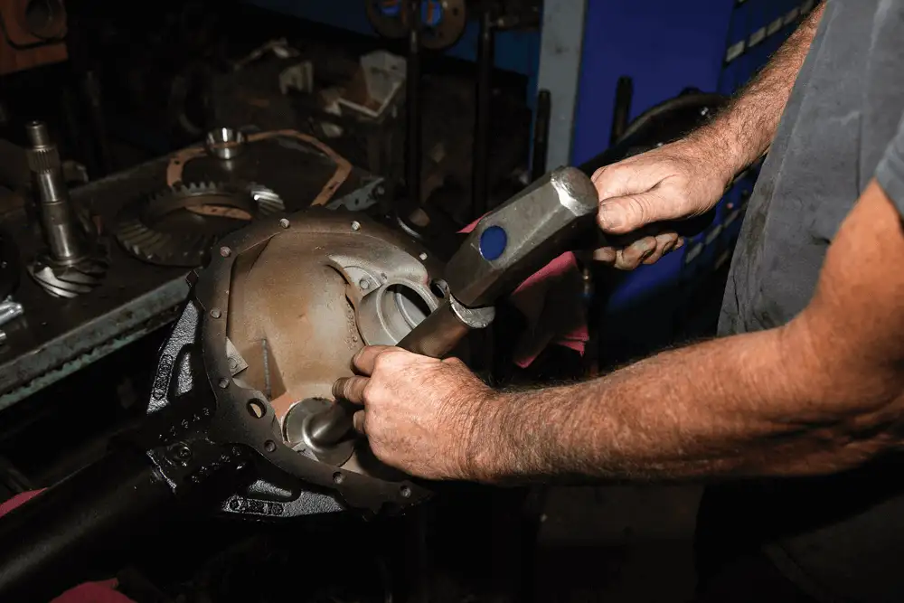
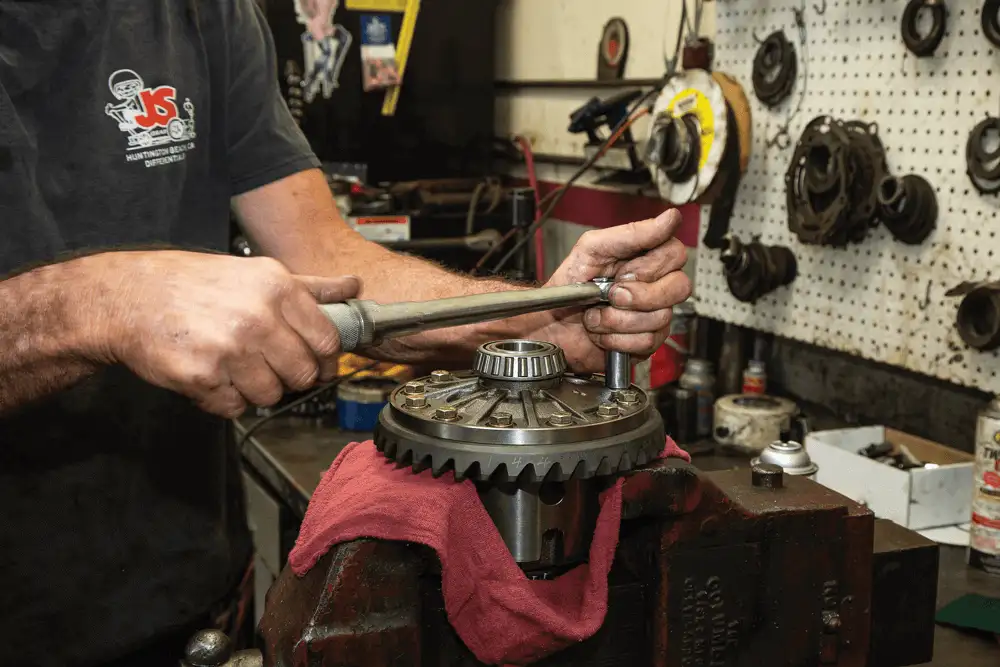
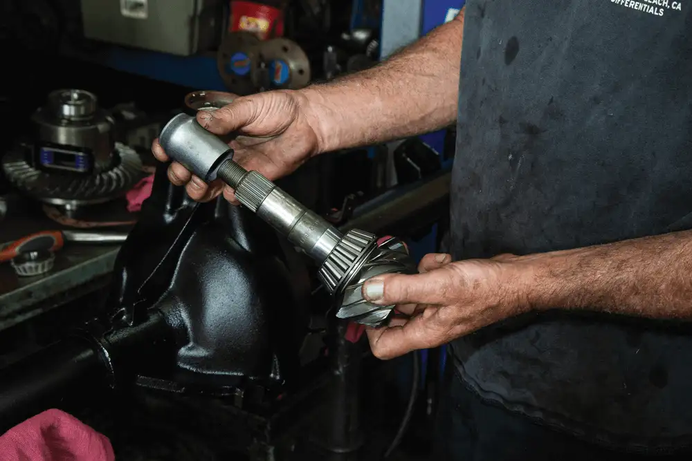
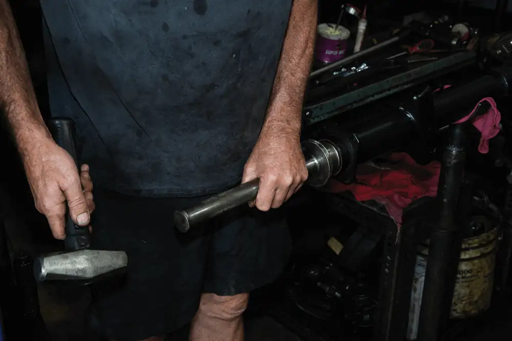
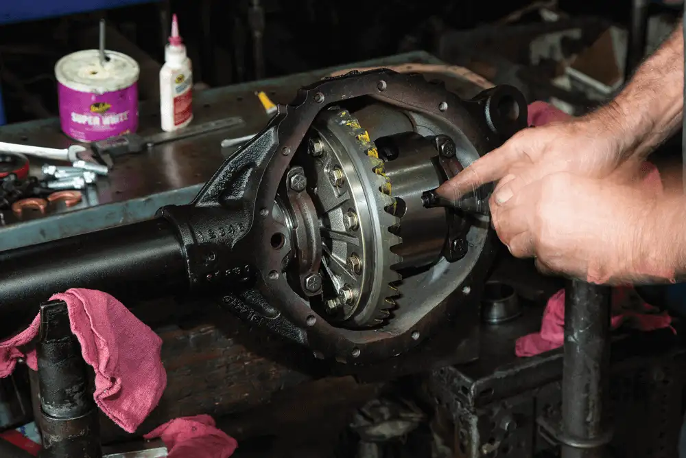
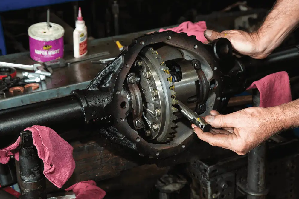
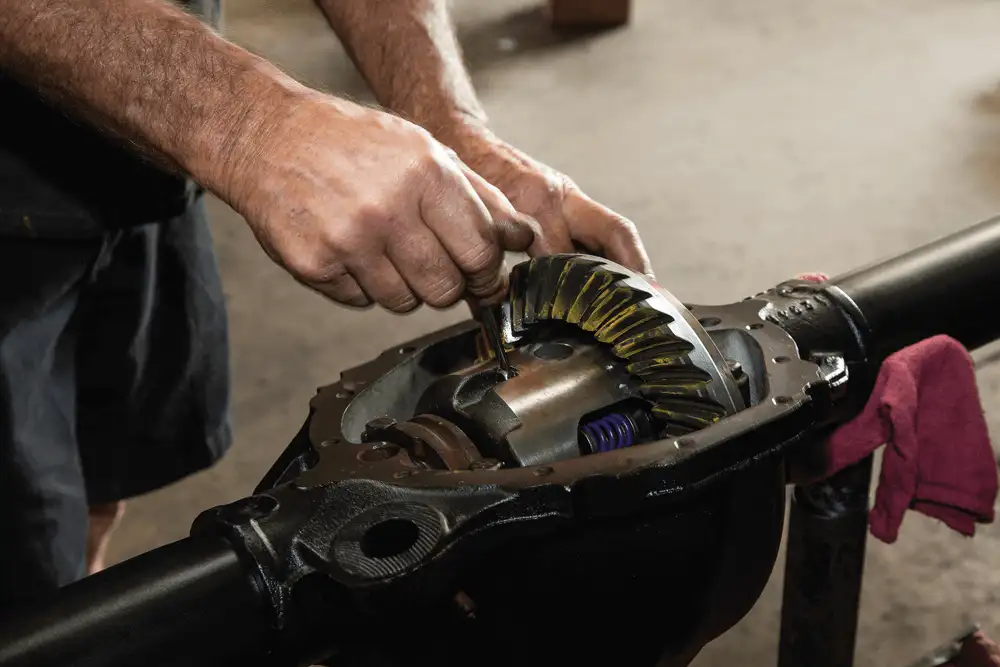
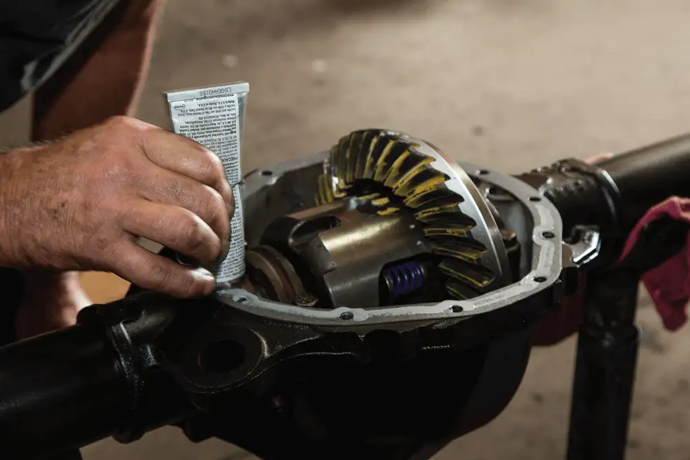
FINAL ASSEMBLY
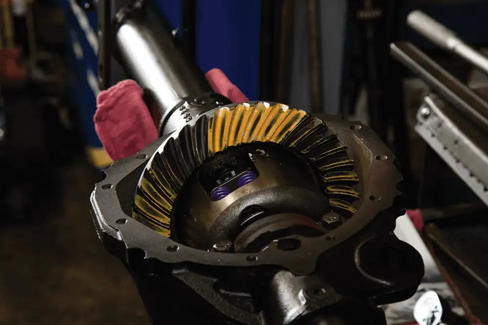
Gear-marking compound was used to check the contact patch and backlash again to ensure it stayed in place during final assembly.


WILWOOD BRAKES
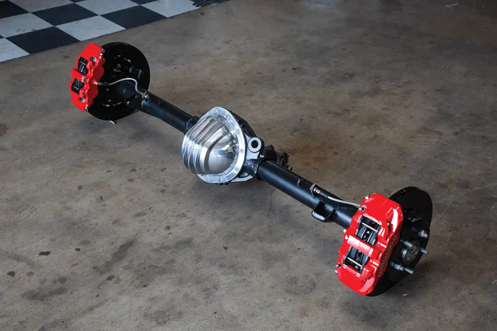
FINAL RESULTS
What are the features of Mark Williams Enterprises’ GM 12-bolt rearend designed for strength?
The GM 12-bolt rearend is engineered with sheer strength in mind, making it a top choice for performance enthusiasts. Here are the standout features that contribute to its durability and robustness:
By integrating these features, the GM 12-bolt rearend excels in providing remarkable durability and performance, ideal for both everyday use and high-stress applications.
How can the procedure of rebuilding a rearend be demystified for enthusiasts?
Rebuilding a rearend can feel overwhelming, but breaking it down into visual steps makes it far more approachable. By following a guided walkthrough with images and detailed captions, enthusiasts can gain a clear understanding of each stage involved.
By presenting the process in a visual and structured manner, hobbyists can confidently undertake rearend rebuilding, transforming complexity into competence.
What are the differences between a 9-inch and a 12-bolt rearend?
Choosing the right rear end for your vehicle can significantly impact performance and durability. Two popular options are the 9-inch and 12-bolt rear ends. Let’s look at the key differences.
Size and Construction
Performance and Durability
Ease of Maintenance
Common Uses
Both the 9-inch and 12-bolt rear ends have their merits and best use scenarios. Your choice will depend on your specific performance needs, maintenance preferences, and the type of driving you’ll be doing. Consider the aspects of durability, weight, and ease of maintenance to make an informed decision for your vehicle.
What are the challenges associated with rebuilding differentials and transmissions?
Rebuilding differentials and transmissions poses several intricate challenges. Primarily, both components contain numerous complex parts that require precise alignment and calibration. Here’s a closer look at the specific hurdles:
Understanding the internal mechanisms of differentials and transmissions is vital. Each system involves a series of gears, bearings, and synchronizers that need to be meticulously inspected and replaced if worn out. Expertise in these areas is essential to ensure smooth operation.
Rebuilding these components isn’t achievable with standard tools. Special instruments like gear pullers, hydraulic presses, and dial indicators are necessary to disassemble and reassemble the parts accurately. Investing in this equipment can be costly for the average DIYer.
One of the most demanding aspects is the precision required. Each gear and bearing must fit perfectly, and tolerances are often measured in thousandths of an inch. An error as minor as a small misalignment can lead to improper functioning or even failure, requiring a redo of the entire process.
The disassembly, cleaning, inspection, and reassembly processes are labor-intensive. Rebuilding a transmission or differential can take several hours to days, depending on the condition and complexity of the unit. This time requirement can be challenging for individuals who cannot dedicate long stretches to the task.
Even with detailed manuals and guides, the risk of improper assembly looms. Missing a step or incorrectly installing a component can cause the vehicle to malfunction. Professional mechanics bring experience and training, reducing the chances of such costly mistakes.
Lastly, without expert knowledge, one might encounter issues that aren’t covered in a manual. Access to technical support from forums, industry experts, or dealerships can be invaluable but isn’t always guaranteed.
Rebuilding differentials and transmissions is a task laden with challenges, primarily due to the detailed knowledge, specialized tools, and precision required. While it’s possible for dedicated enthusiasts to undertake this work, it often proves more efficient and effective to rely on professional mechanics.
What basic understanding is necessary for the operation of differentials and transmissions?
To grasp the functioning of differentials and transmissions, a foundational knowledge of their core principles is essential.
These understandings form the backbone of vehicle mechanics, giving one the tools to appreciate how these systems contribute to overall performance and handling.
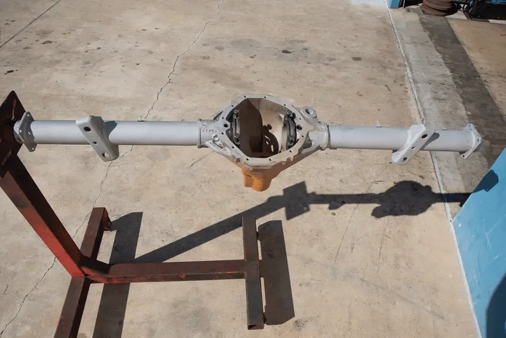
How are leaf-spring pads located and welded to the axle tubes in a 55 Chevy pickup?
To locate and weld leaf-spring pads to the axle tubes in a ’55 Chevy pickup, you’ll start by ensuring the axle housing is fully cleaned and prepared. Here’s a step-by-step breakdown:
Taking these steps ensures that the leaf-spring pads are securely and accurately located and welded to the axle tubes, promoting proper alignment and functionality in your ’55 Chevy pickup’s suspension system.
How can a Chevrolet C10 rearend be made bulletproof?
Chances are your truck has a 12-bolt rearend, but if not, it’s fairly easy to get your hands on one. Not only are they common, but they can also be pretty solid when built correctly. In fact, they can stand up to around 800 hp, which is perfect for a street truck with some performance mods under the hood. Thirty-spline axles and a large ring gear help these rearends hold power. They also require less power to turn because of the height where the pinion gear contacts the ring gear.
To make your Chevrolet C10 rearend bulletproof, you need to focus on several key components:
Strengthening the rearend housing is the first step. Upgrading to heavy-duty axle tubes and adding gussets can significantly increase the rigidity and durability of the rearend.
Install 35-spline axles for added strength. The additional splines provide a larger surface area, which helps distribute the load more evenly and reduces the risk of breakage.
One drawback to running a factory rearend is the open differential. It will allow the wheels to rotate at different speeds for a smooth ride, but it will also transfer power to the wheel that has the least traction. This isn’t ideal when you’re trying to get the maximum amount of power transferred to both rear wheels.
To combat this, we ordered a Yukon Dura Grip positraction differential (P/N YDGGM12T-4-30-1), which uses a set of springs to lock two packs of clutches in order to distribute power more evenly between the two separate wheels. This upgrade ensures that power is efficiently transferred to both wheels, enhancing traction and performance.
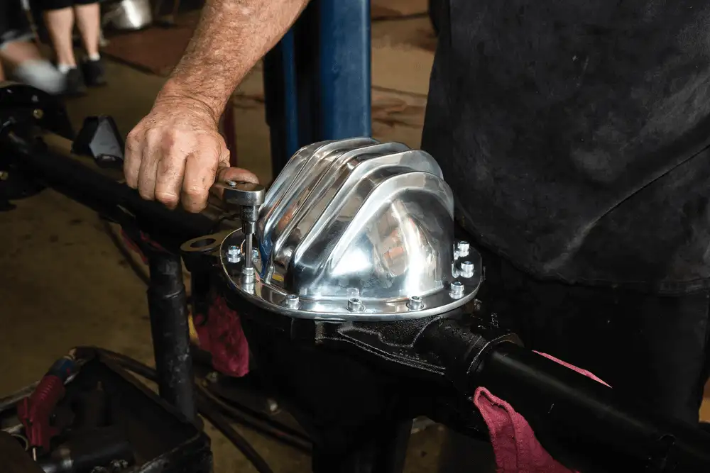
A girdle cover is an effective way to add strength to the rearend. It helps to prevent deflection and keeps the gears properly aligned, which is crucial for maintaining the integrity of the rearend under high stress.
Using high-quality gear oil and installing a rearend cooler can help manage the heat generated from high-performance driving. Proper lubrication reduces friction and wear on the components, extending the life of your rearend.
After a simple rebuild, our rearend was ready to go, moving our project faster and stopping it better. Once complete, we had a rearend that was strong enough to hold decent power and transfer it to the rear wheels for maximum traction. With these upgrades, your Chevrolet C10 rearend will be bulletproof, capable of handling increased horsepower and providing reliable performance.
What is the importance of professional expertise in the rebuilding of driveline components?
To help us build our rearend, we took everything to J and S Gear in Huntington Beach, California. John Coulman is the man with a plan with more than 30 years of experience building rearends. Not only is he a top-notch rebuilder, he can also narrow rearends to fit specific wheel/tire combos.
While talking with John, we discovered that he got into his profession by doing what most of us do: hammering on our vehicles and breaking parts. After watching him build this 12-bolt rearend in just a few hours, we can confirm that he knows his stuff.
Sure, I’ve always had a basic understanding of how they operate, but I’ve always left these particular chores in the capable hands of professionals and never bothered to actually investigate what’s really involved. Watching Johnmeticulously work on our rearend, it became clear why professional expertise is invaluable. His precision and efficiency are the results of years of dedicated practice and specialized knowledge.
John’s ability to rebuild and customize rearends quickly and accurately is not something most of us can achieve without extensive experience. This is why relying on professionals for such intricate tasks ensures the job is done right the first time, saving time, money, and headaches in the long run.
What is the role of professional expertise in ensuring task completion?
Professional expertise is seen as crucial for the proper completion of the task, ensuring that it is done accurately and efficiently, which might not be guaranteed if attempted by someone with only a basic understanding.
How does the author view the complexity of the task?
The author perceives the task as complex enough to warrant professional attention, suggesting that a more detailed investigation and understanding are required than what they possess.
What is the level of understanding of the task by non-professionals?
Non-professionals may have a basic understanding of the task but typically do not delve deeply into the complexities involved, often preferring to leave it to those with more expertise.
Why might someone choose to rely on professionals?
People might rely on professionals because they trust in the experts’ skills and understand that these tasks require specialized knowledge and experience that they might not possess.


We use cookies to enhance your browsing experience, serve personalized ads or content, and analyze our traffic. By clicking "Accept All", you consent to our use of cookies. Visit our Cookie Policy for more info.


Share Link