 MARCEL VENABLE
.
February 18, 2026
.
c10
.
MARCEL VENABLE
MARCEL VENABLE
.
February 18, 2026
.
c10
.
MARCEL VENABLE
Alot of truck lovers forget that in the mid-’60s it was muscle cars, not trucks, which made a lot of horsepower. For the most part, trucks were an engineering afterthought whose purpose was strictly to serve as work vehicles. Today the tables have turned, and many truck lovers have installed parts to generate more horsepower from their two-door specials than even the fastest muscle cars from the golden age of cheap gas could conjure.
Modern power plants have become increasingly more reliable, yielding more power than ever, and the same goes for modern suspensions and rear differentials. So it makes sense to outfit your truck with a sturdy chassis, a firm suspension and an extra strong differential to match your new powerful engine swap.

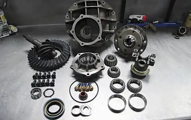
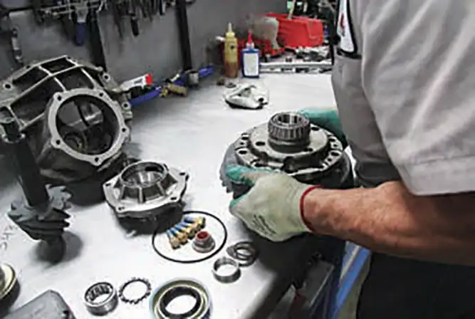
Outfitting the rear of your C-10 to accommodate more horsepower is easier than you might think. Many manufacturers have developed paired components to handle all of the power. In the past, items that were able to handle power had to be custom built to order, taking in considerations such as, make and model, tire size, and even the owner’s driving style.
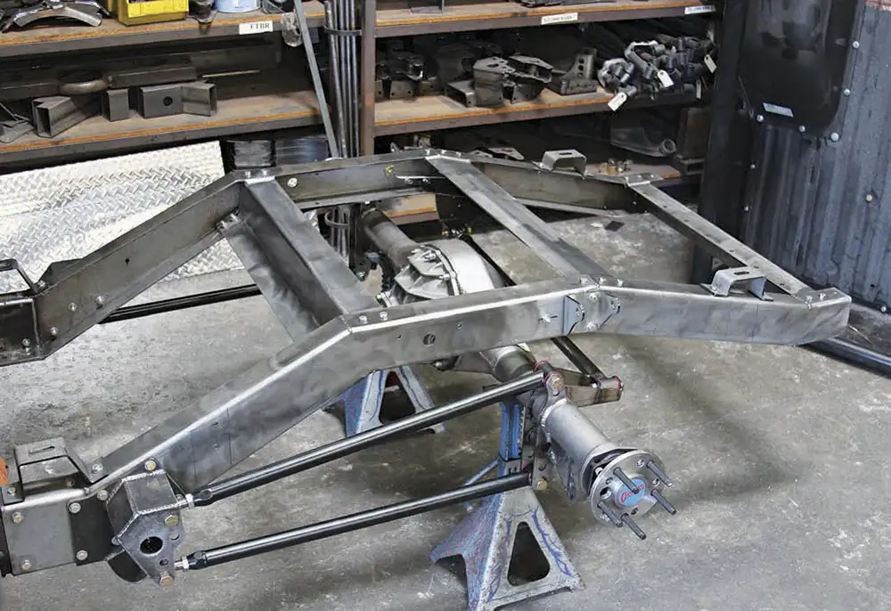
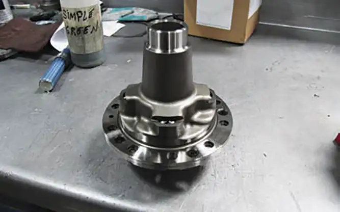
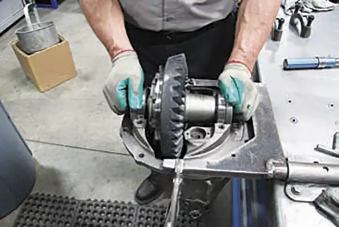
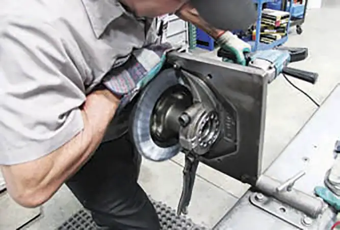
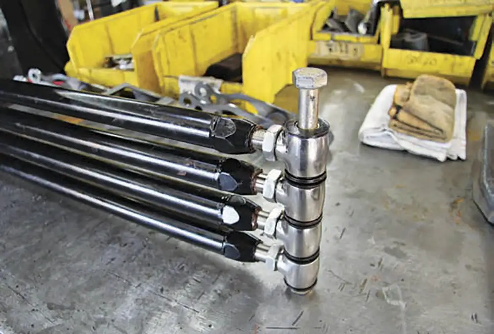
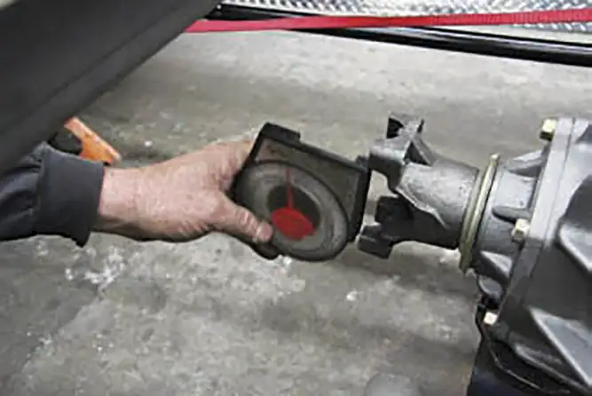
Hands down one of the best combos to handle power has been the Ford 9-inch rear differential paired with a 4-link suspension system. In the racing world these two are a better pair than peanut butter and jelly because they seem to work well under any type of vehicle and can really take a beating.
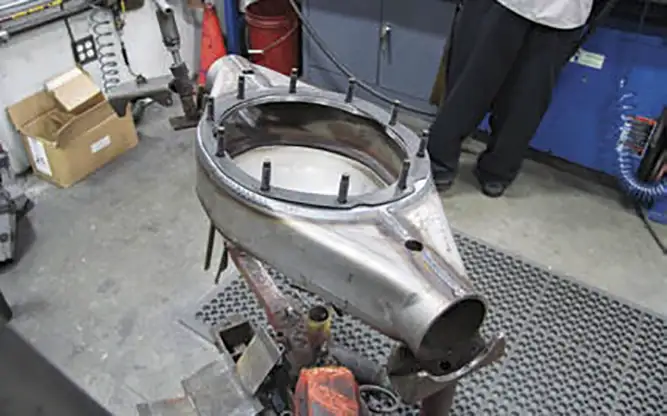
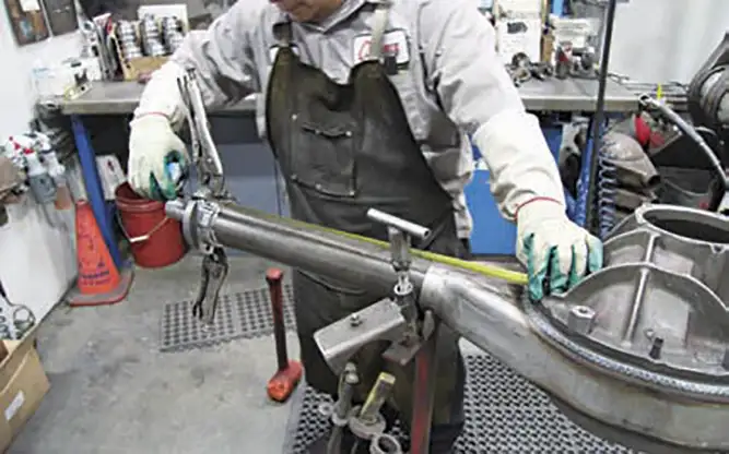
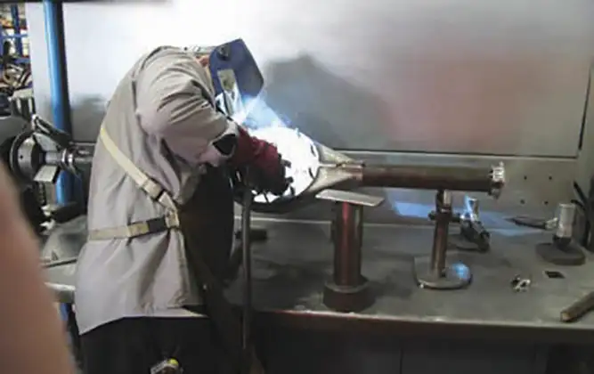
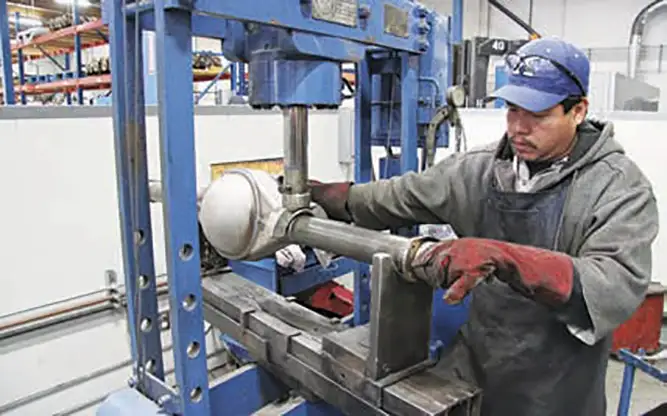
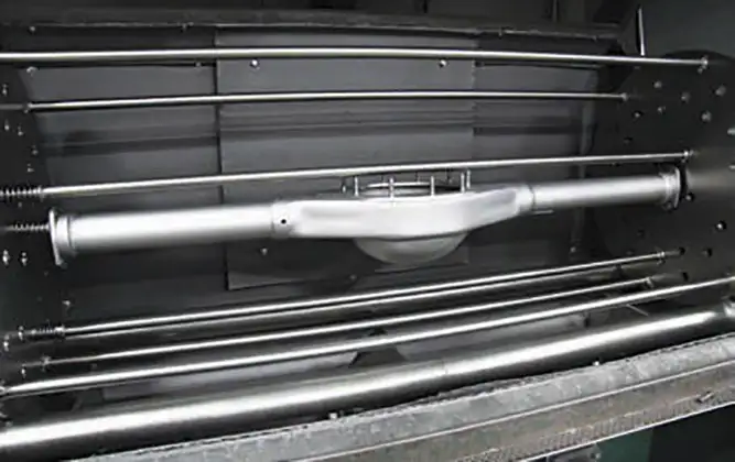
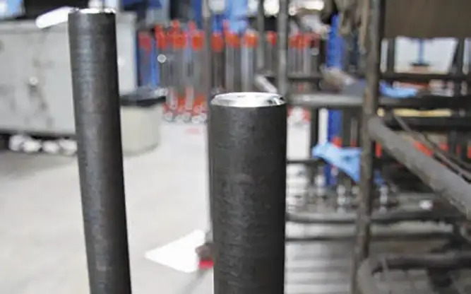
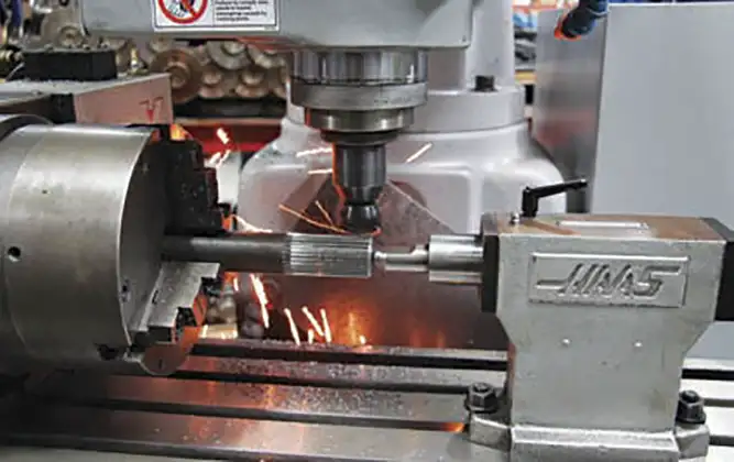
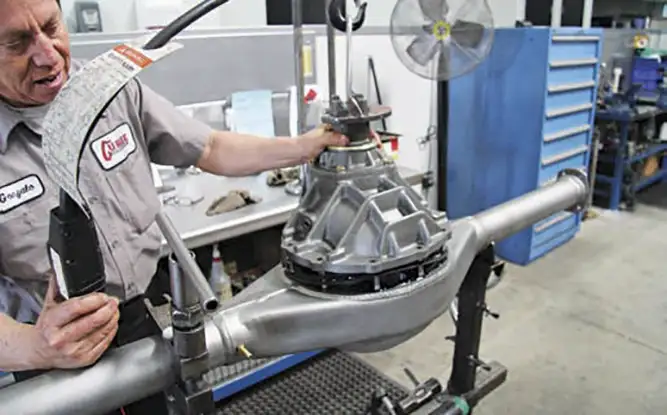
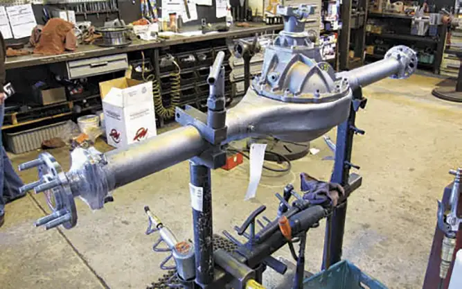
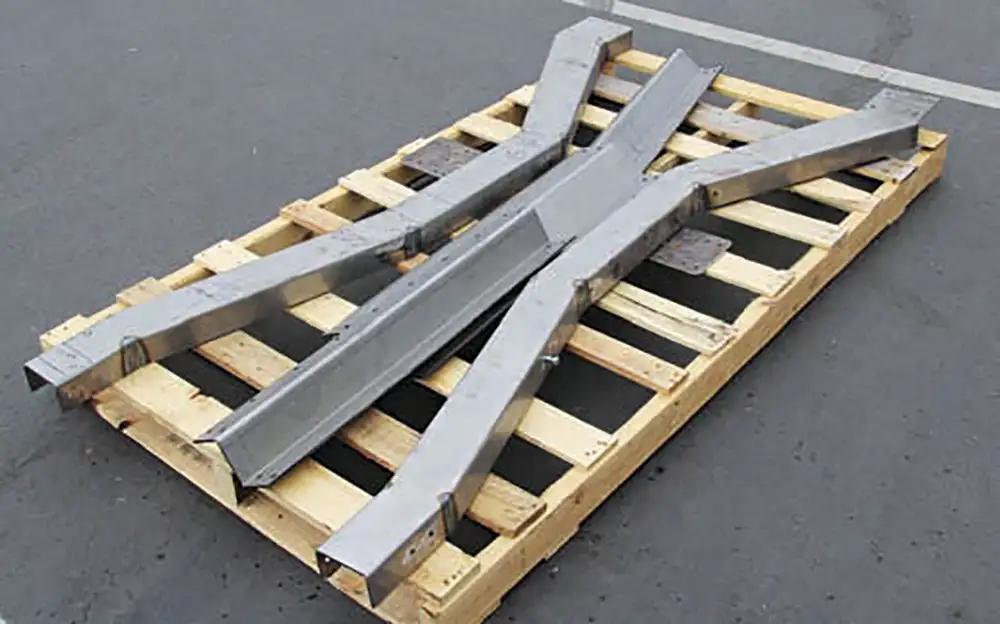
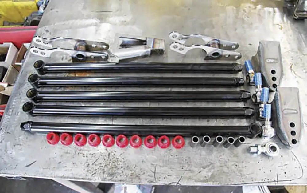
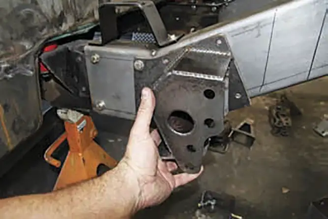
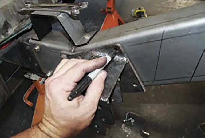
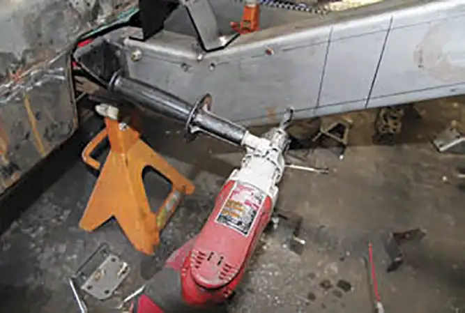
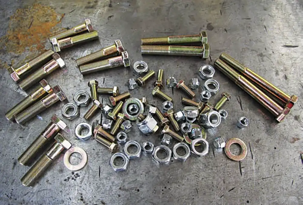
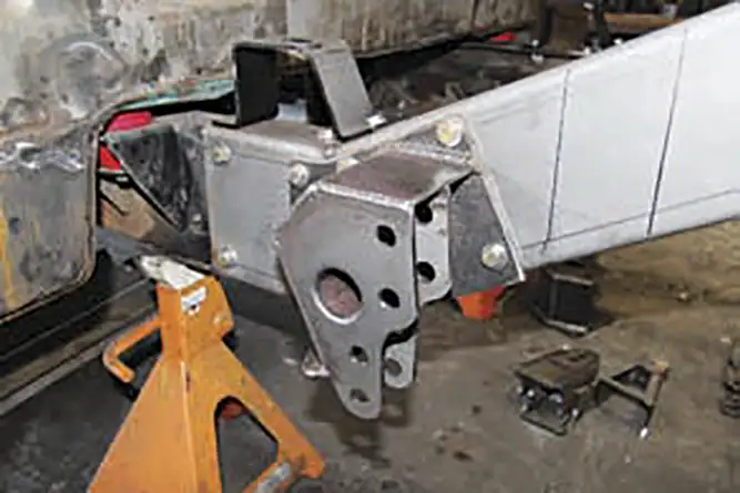
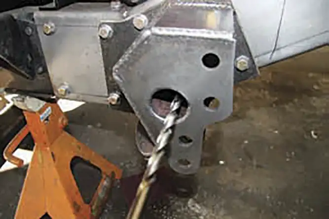
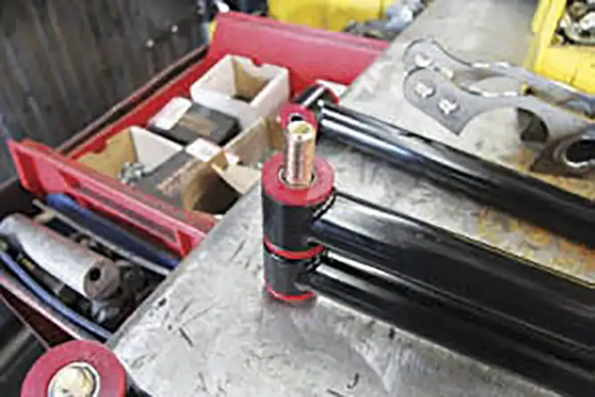
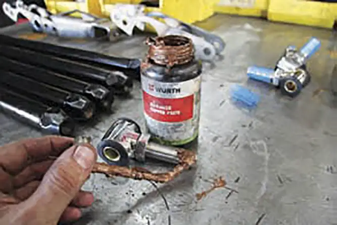
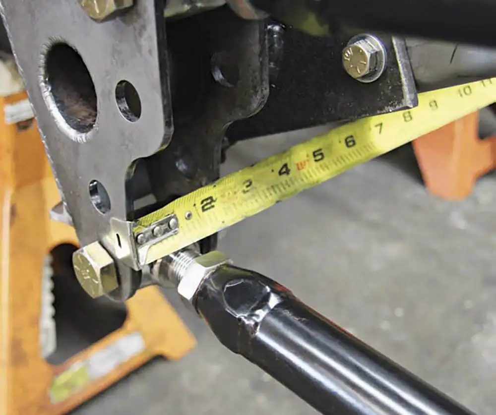
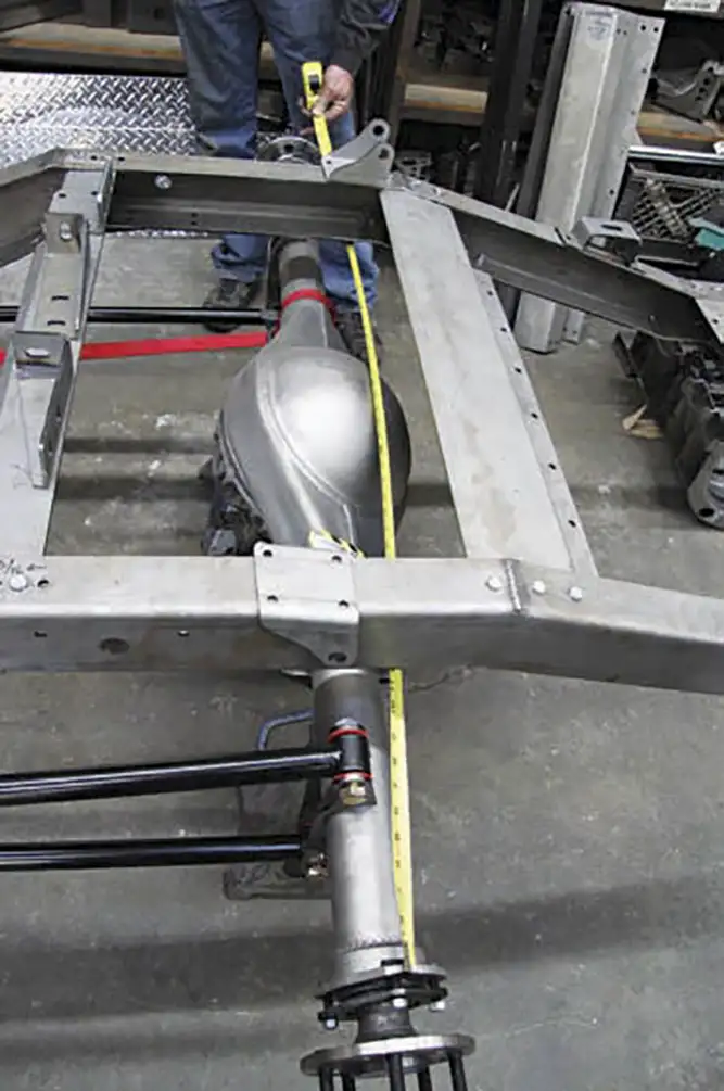
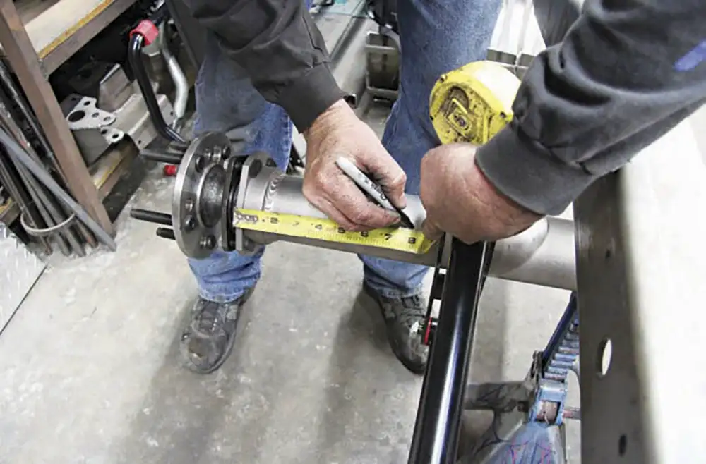
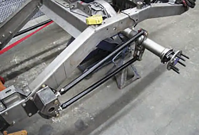
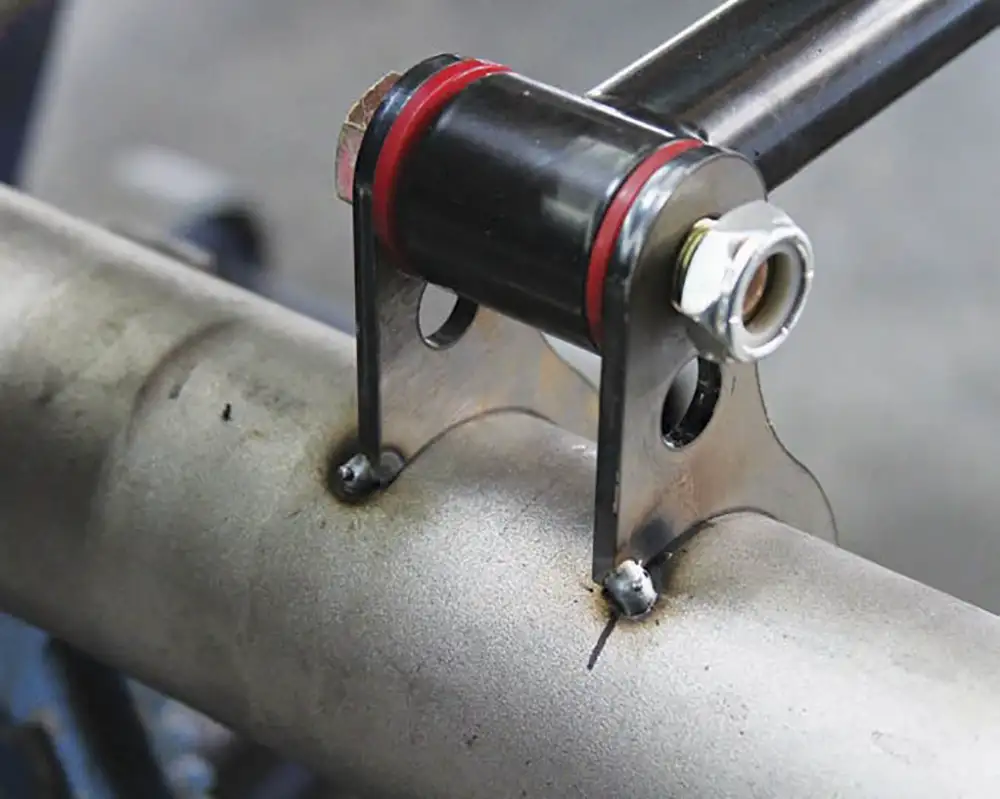
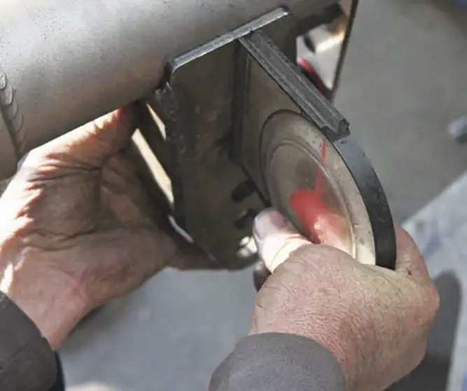
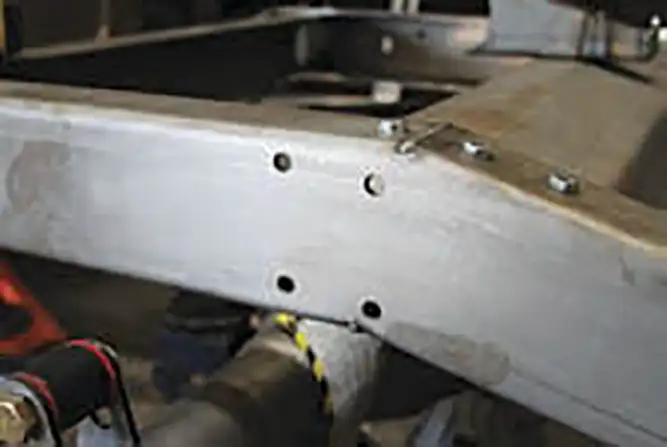
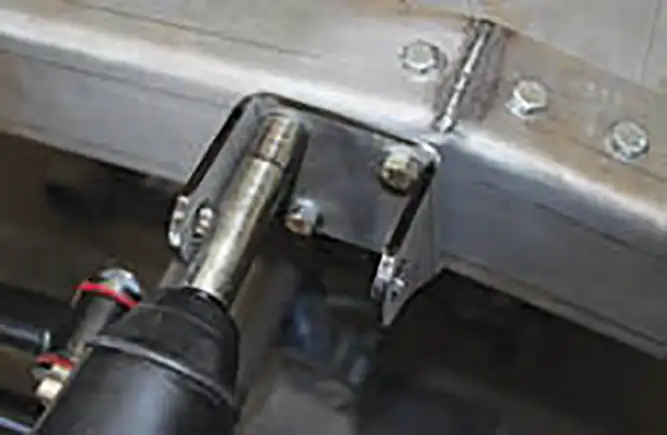
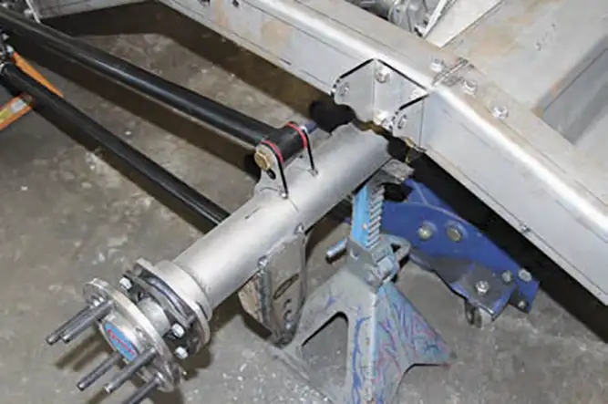
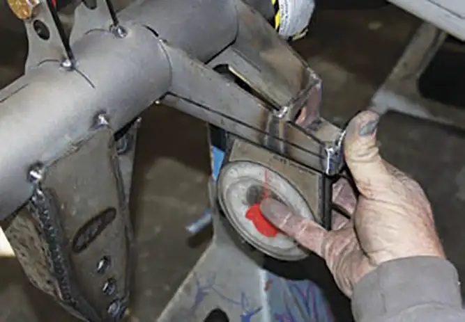
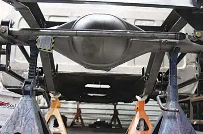
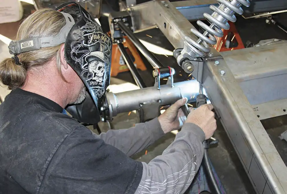
We wanted to show you just how easy it is to install this pair on the back of a ’68 C-10. We ordered a Currie Enterprises 9-inch Ford-style housing built to our specs that allowed us to squeeze 12 ½ inches of rubber on either side of the bed. Connecting and directing all of the power from the engine to the diff is No Limit Engineering’s Fat Bar 4-link system. No Limit’s kit has everything you need to mount a 4-link-style suspension to your C-10-based vehicle, including an adjustable panhard bar that will allow you to tune your truck to handle more torque and smooth out the tight curves. ST
CURRIE ENTERPRISES
Currieenterprises.com
EATON
Eaton.com
MOTIVE GEAR
Motivegear.com
NO LIMIT ENGINEERING
Nolimit.net

F100 Builders
It Only Took a Dozen Years of Careful Refinement! The process of creating a custom truck usually begins with a series of ideas accumulated over… Continue reading
Joe Greeves . September 04, 2024
Department
Mark Your Calendars and Get to Cleaning 2025 National Event Schedule MAY May 2-3 Kickin’ It In Kentucky Splash Williamsburg, KY May 3 C10s in… Continue reading
STREET TRUCKS STAFF . June 10, 2025
Features
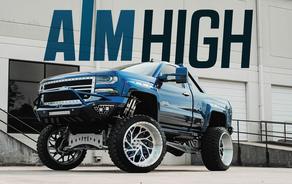
A Single Cab, Twin-Turbo Skyscraper! rowing up 30 years ago was a lot different than it is today. Without cell phones and social media, the… Continue reading
Chris Hamilton . June 09, 2022
Features
Taking a truck from modified daily driver to something show worthy can be a hard transition for vehicle owners. Committing to take that build as… Continue reading
streettrucks . January 15, 2020
Blood Sweat and Gears
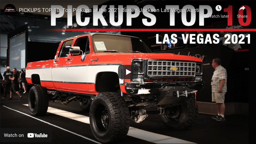
From stock and mild to inventive and wild! The 2021 Barrett-Jackson Las Vegas Auction was home to some of the hottest pickup trucks around. Today,… Continue reading
Adam Johnson . November 08, 2021
c10
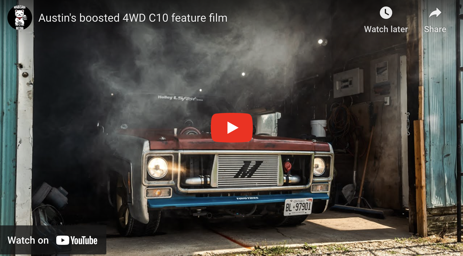
Check out this labor of love and see Austin’s boosted 4WD C10 truck in this film about the build process and its ups and downs!… Continue reading
STREET TRUCKS STAFF . December 05, 2022


Share Link