TECH THIS OUT! | ’49 CHEVY GETS AN S10 CHASSIS SWAP
JEREMY RICE . August 20, 2020 . Editor
Share Link
Save ArticleLogin to save it
While looking into chassis and suspension upgrades for our ’49 Chevy 3100 Advance Design pickup, we came across Robert Hertz from ADEngineering. There are several options out there for these trucks, from brand-new chassis to weld-in Mustang-II-style front cross members, and some people have even cut the front frame off and clipped them with Camaro or other Chevy-car-style front suspensions.
Robert actually approached us to inform us of a chassis swap kit he produces for the 1947-55 first series pickups and Suburbans. We were definitely intrigued and started talking about using the kit for project Cindy.
After exchanging a few emails with Robert, we were sold on the chassis swap kit. The complete kit comes with everything we would need to swap the chassis, engine, transmission and steering. AD-Engineering has spent a lot of time perfecting the kit, both on the computer-generated plans as well as on vehicles. We selected the options we would need for our project and the parts were soon headed our way.
The swap kit from ADEngineering is designed to work with a standard cab long bed S10 chassis. The 1982-93 model years are a bit easier to perform the swap with, but the 1994- 2005 will work just fine as well. The difference between the two model years is that the earlier versions are not boxed in as far back, making it easier to get to the new bolt locations.
If we were to get a hold of a second-generation model we would have to drill access holes, but it’s still very doable. Luckily for us, we were able to track down a retired airport service truck. The truck had seen a lot of use, but it was never involved in an accident because it was always used inside the airport. This, combined with a visual inspection, assured us we would have a straight chassis with which to work.
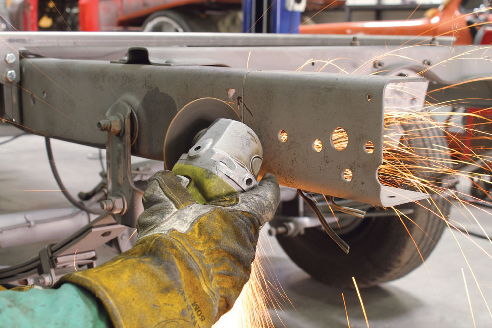
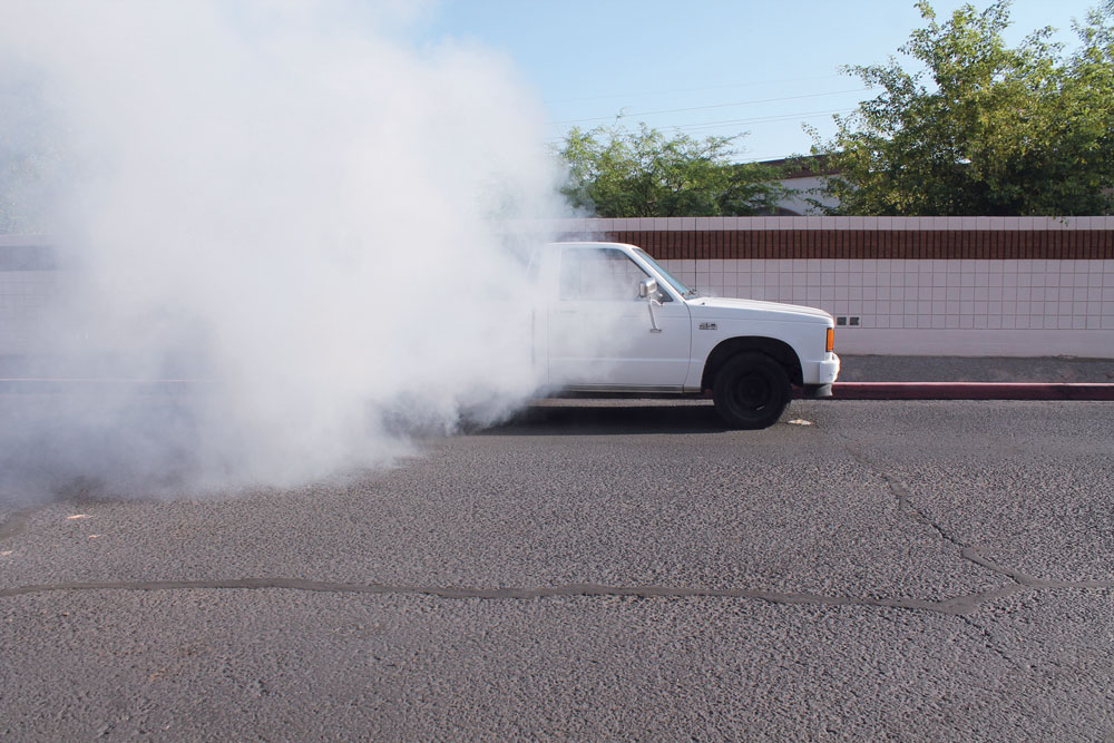
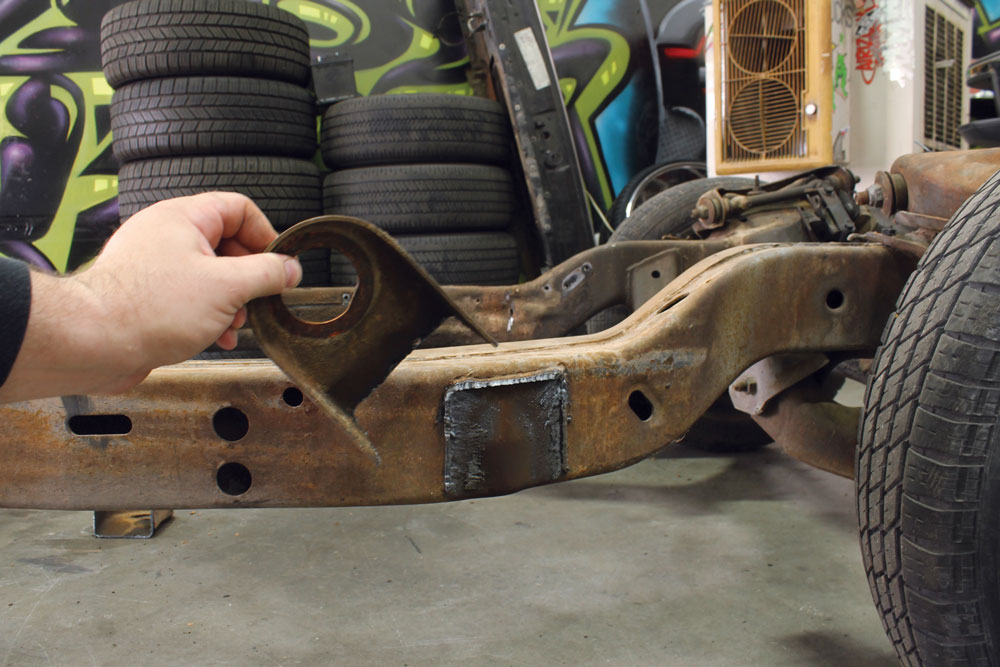
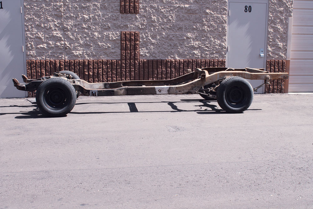
Here’s the donor truck. This 1986 standard cab long-bed S-10 was the perfect candidate for our chassis swap. We picked it up for $450 and it was still running and driving. It did have a blown head gasket, but that didn’t stop us from attempting to completely blow up the engine with a nice burnout.First we stripped the donor truck down to a rolling chassis, and then we began prepping the frame for the new mounts. The rear cab mount and forward bed mount were the first to go. A plasma cutter made quick work of the bulk of the material.We then came back with a cut-off wheel to remove the smaller parts of the mount. Finally, we finished cleaning up the frame with a flap disc sander.The same process was performed on the front mounts as well. There’re also a couple of smaller items, like the rear bump stops, that can be removed at this time as well.After a total of about five hours here’s what we ended up with: the complete rolling chassis, cleaned up and ready for some new brackets and hardware.
REAR BODY MOUNTS
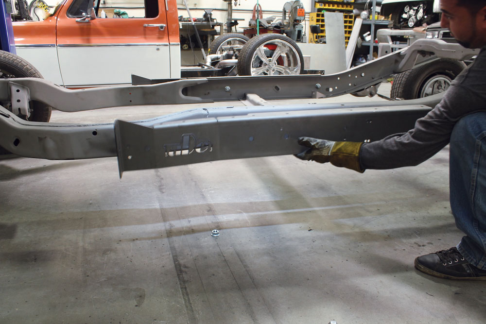
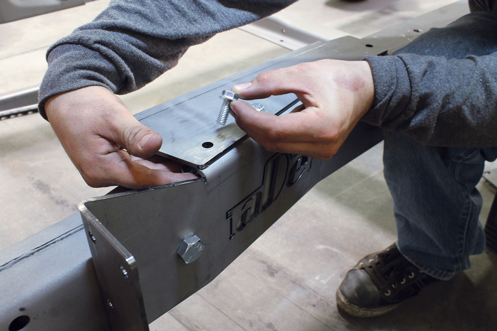
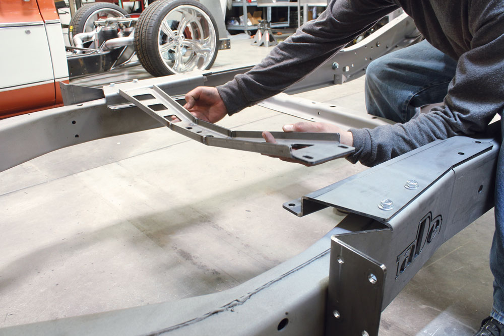
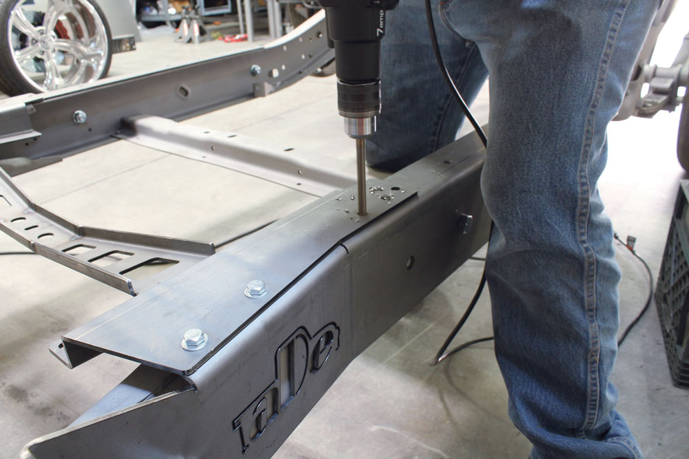
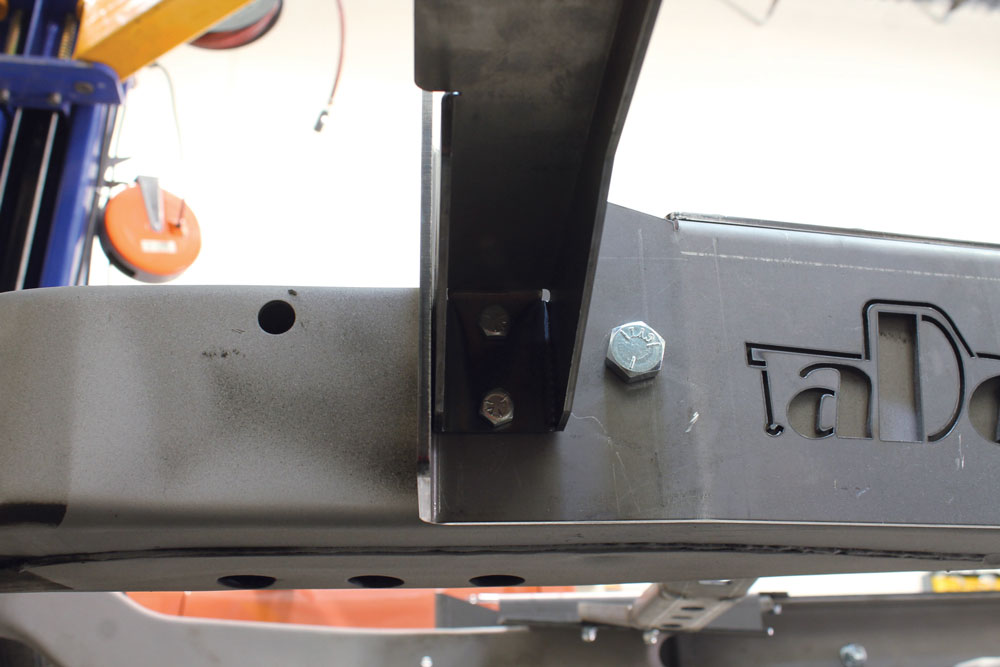
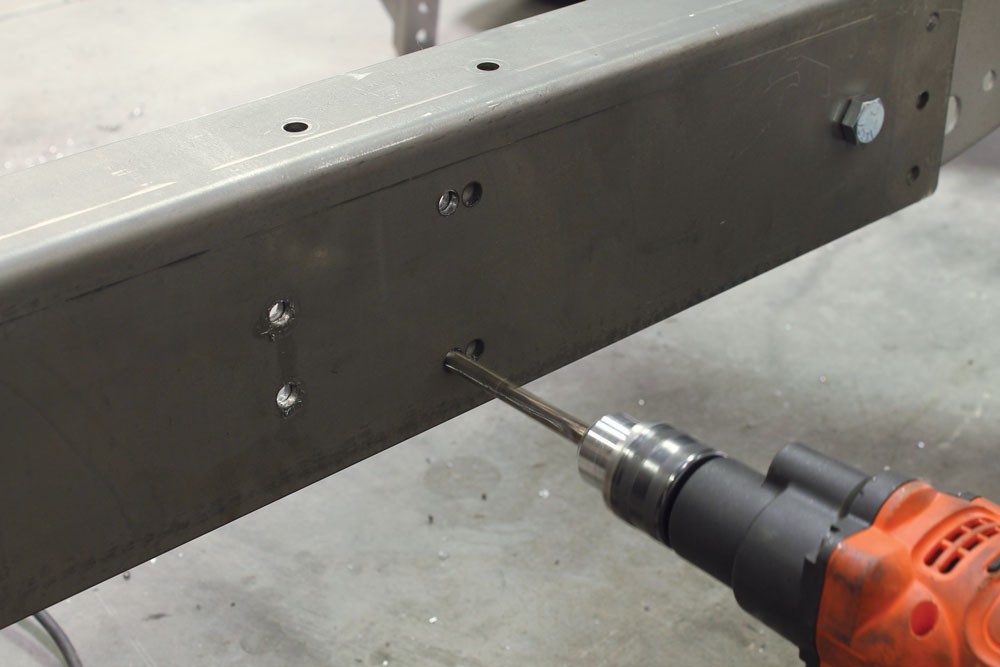
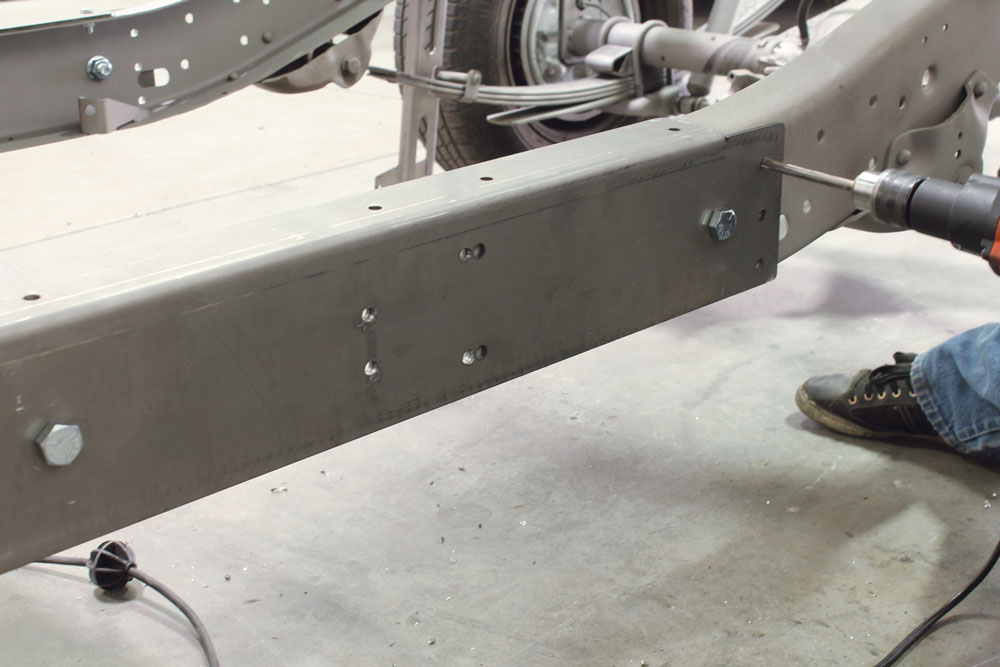
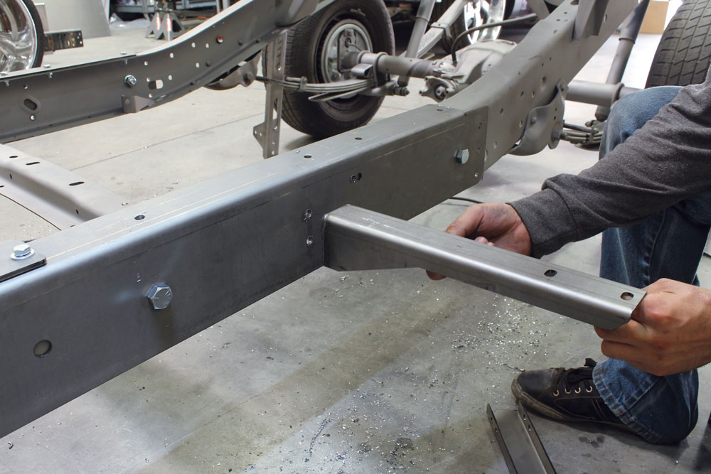
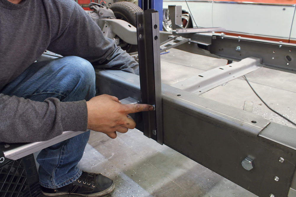
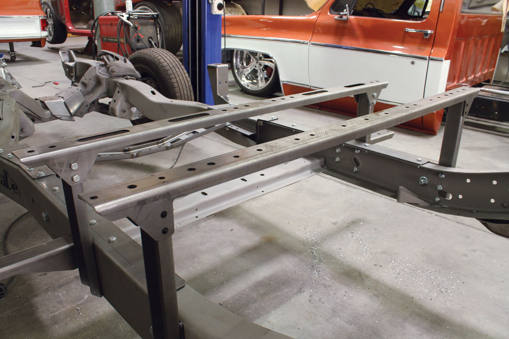
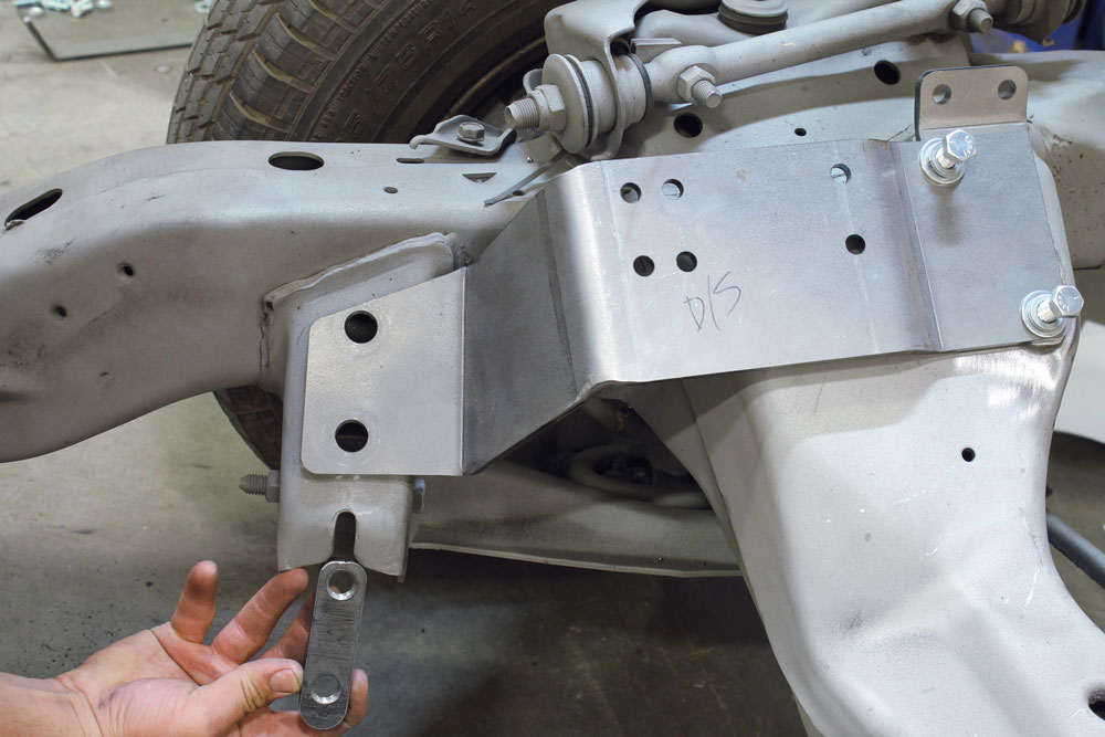
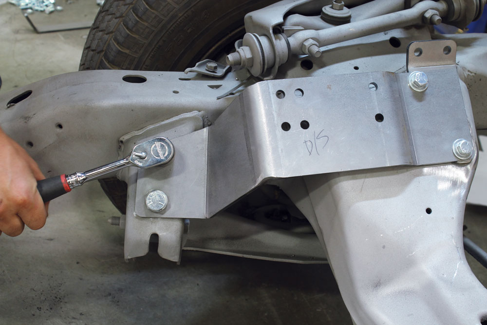
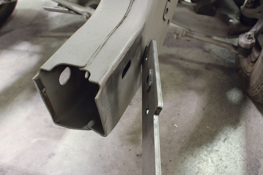
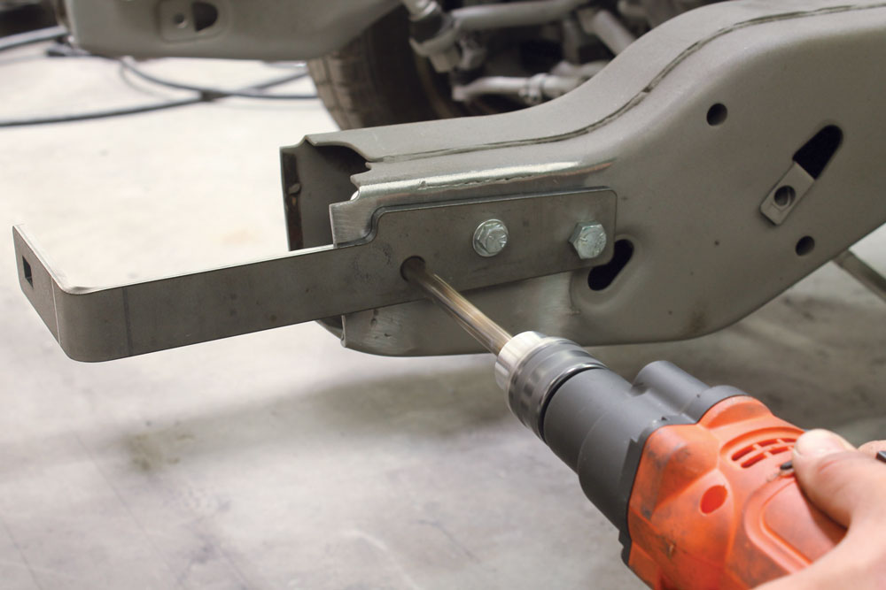
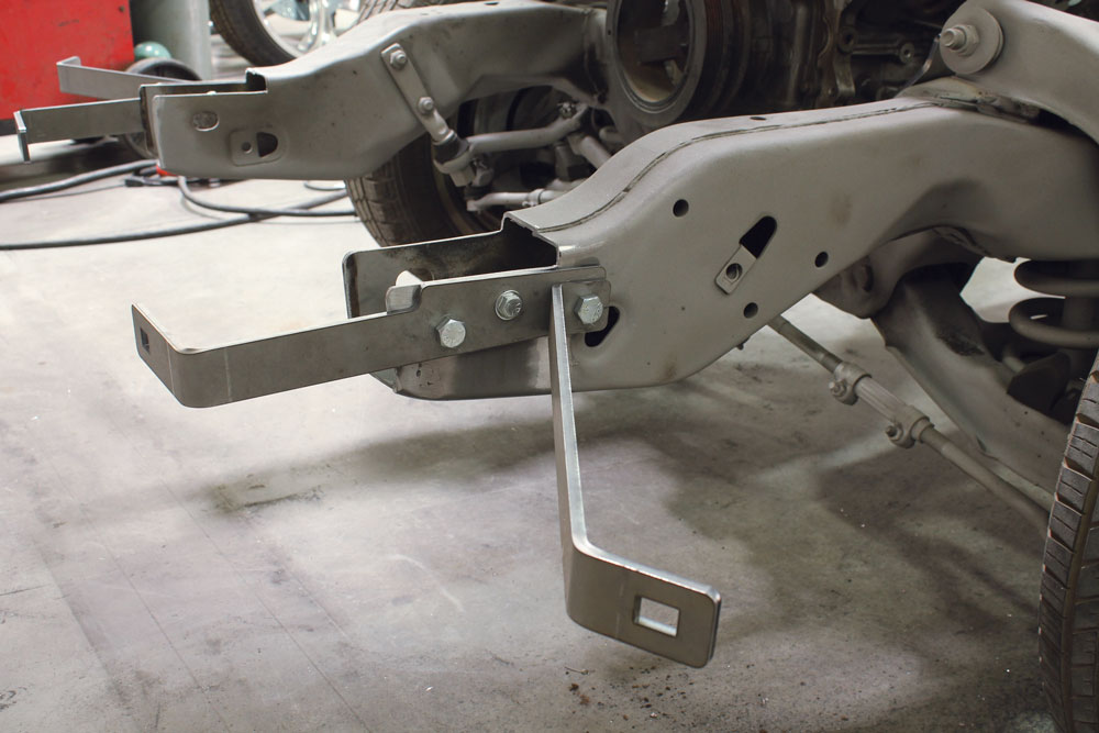
The main bracket for the chassis swap almost completely covers the side of the frame rail. The piece is held against the side of the frame rail and three bolts secure it to the frame through factory S-10 frame holes.Next up, we set the transmission cross member mounts in place and loosely bolted up the forward two bolts.The transmission cross member was placed between the mounts and loosely bolted in place.Once we had the three pieces bolted together and aligned properly, we drilled the rearward two holes through the mount and the top of the frame rails. The loosely installed bolts were then tightened, locking the transmission cross member in place.Moving towards the front end of the main bracket, we drilled new holes in the frame for the front running board mounts. The running board mount was then bolted in place with the two bolts that pass through the S-10 frame rails.These bolts were probably the most difficult part of the installation. Make sure you have someone with long skinny arms that can get their hands far enough up the opening of the frame to hold a wrench on the back of the bolt. If you don’t have someone like that to help you out, you could drill an access hole for a socket on the boxed section of the frame.The front cab mount shares a couple of bolts with the running board mount. We were impressed with how these pieces fit together even though we were mounting several pieces together at once.Next we moved towards the rear of the frame rail. The main bracket locates several more holes along the way towards the rear of the truck. The forward two in this photo are for the middle running board bracket. You’ll notice the ones we are drilling in this photo are the two closer to the front of the truck in the set of four. The ones directly behind are for the Suburban mounts, so those did not need to be drilled.There were also several holes along the top of the main bracket that needed to be drilled. These bolt holes are more for attachment strength of the main bracket. The final holes in the main bracket are all the way towards the rear of the truck and will attach the forward bed mount.With all of the new holes drilled, we started attaching more new brackets. These mounts will serve as the middle running board mounts.
REAR BODY MOUNTS
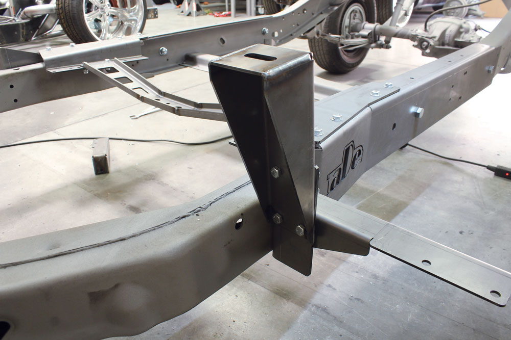
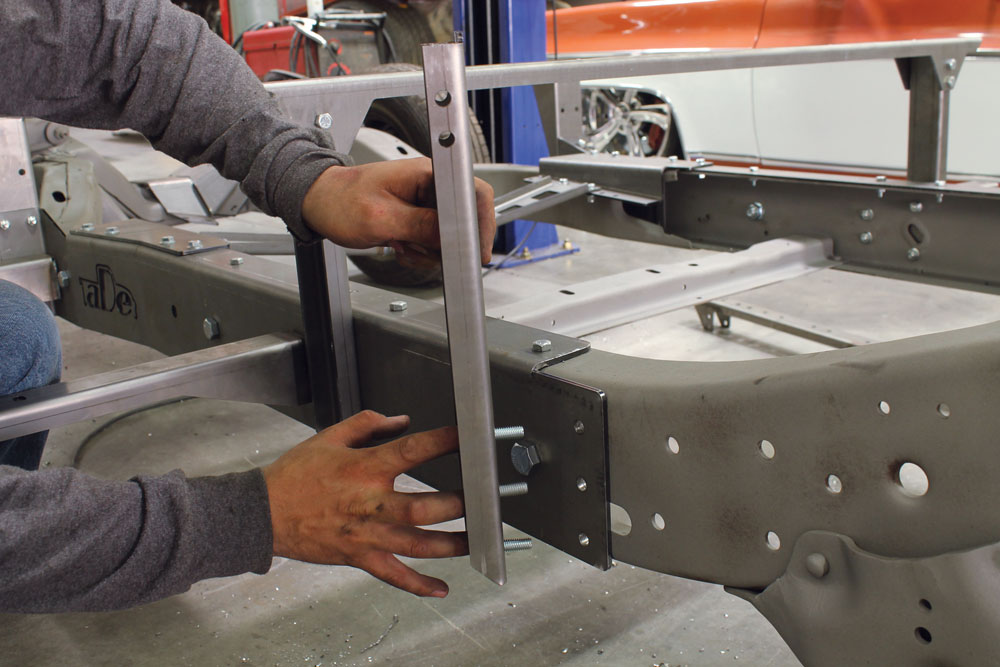
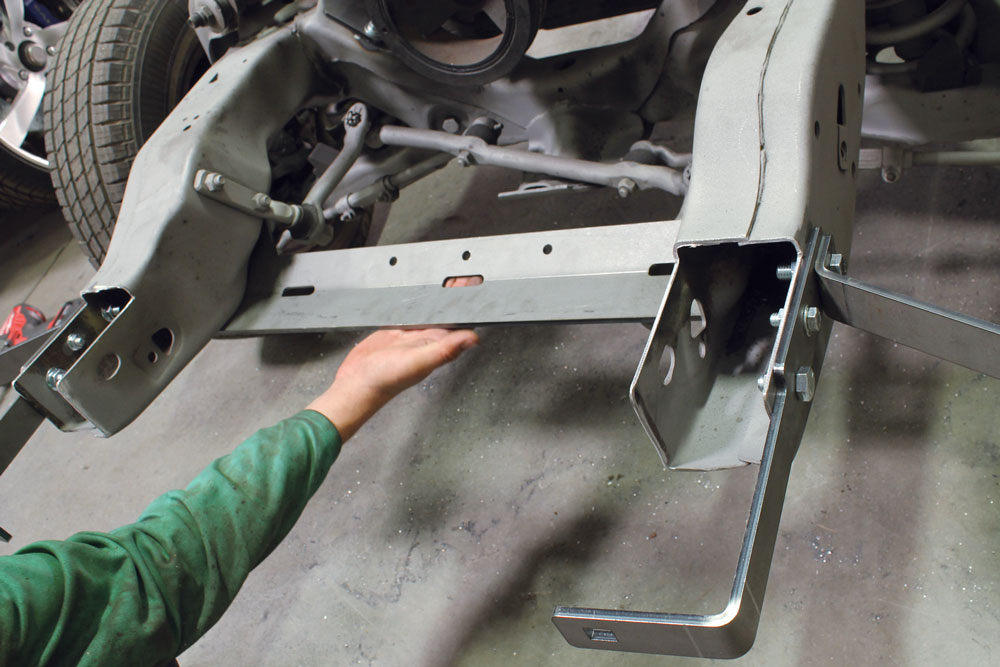
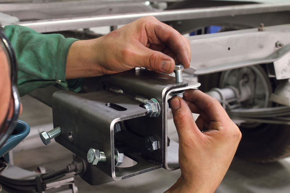
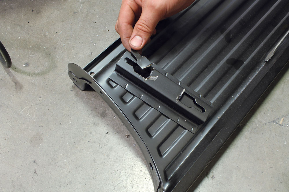
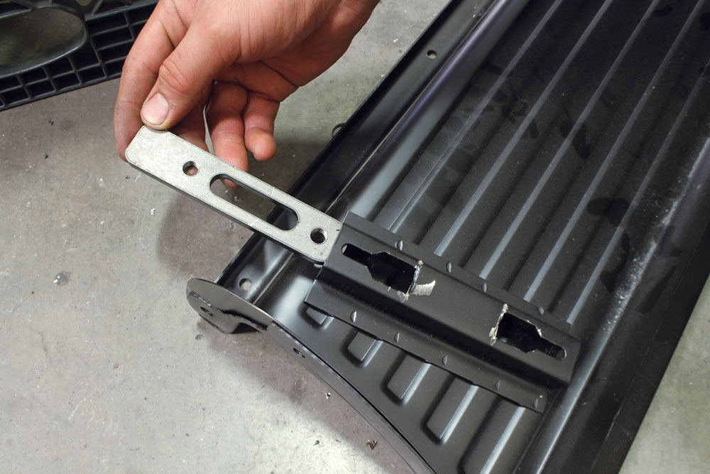
Following up the running board mounts were the rear cab mount brackets. Again, we used the provided hardware and mounted them through the newly drilled holes.The rear cab mount cross member was placed on the vertical mounts that have tabs in them that key into holes cut in the cross member. Four bolts attach the cab mount cross member to the vertical mounts.Finishing off the mounts that use the main bracket are the forward bed mounts. The vertical pieces were installed in the same fashion as the rear cab mounts.Just like the rear cab mount, the forward bed mount is comprised of a cross member that bolts to the vertical pieces on each side of the frame.When we unpacked the boxes we were kind of confused as to its purpose. However, once we read through the detailed instructions included with the kit, we learned that it was meant to be used as a jig to drill more holes. Notice the plate is even labeled, so there’s no way we could install it the wrong way. We used the same jig plate on the opposite side of the frame.Once we had all of the new holes drilled through the frame, the jig plate was removed and the remaining bed mounts were installed. These went on just like the first . All of the pieces are keyed together so it’s nearly impossible to get this installation wrong.
ENGINE MOUNTS
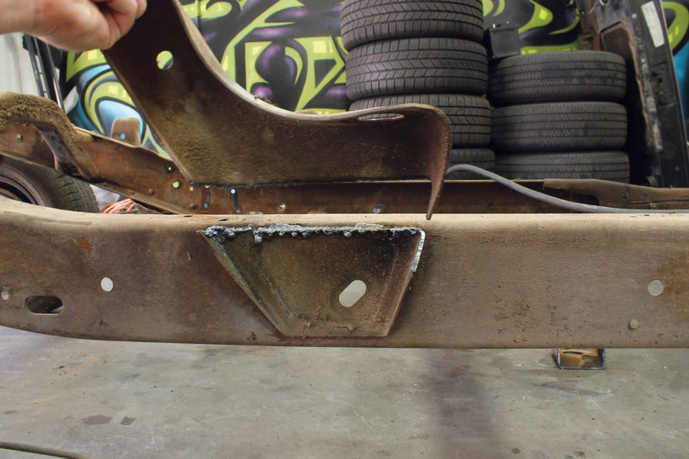
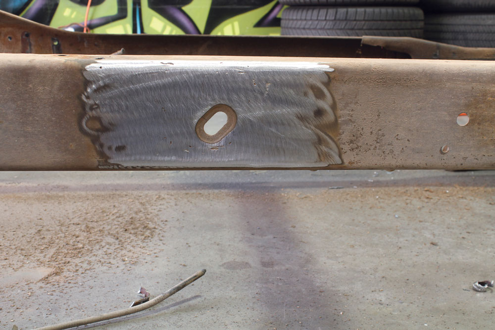
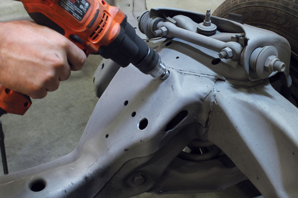
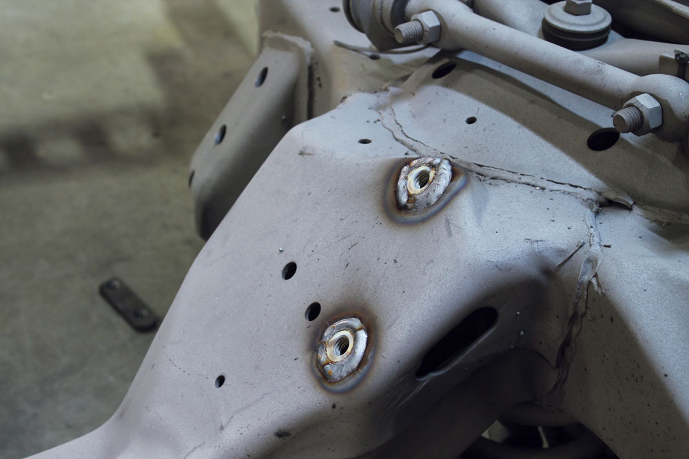
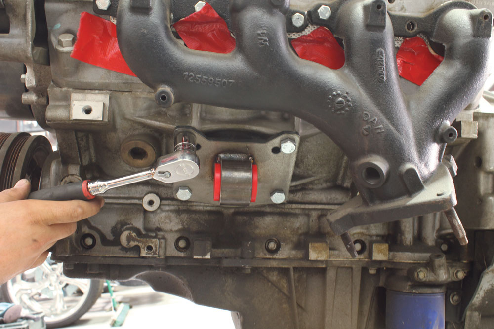
Moving towards the front of the truck again, we began to work on the engine mounts. Robert gave us the idea to drill out the factory engine mount holes and weld in nuts to make installation easier. We decided to go ahead with this plan and began by drilling holes large enough for the flange nuts to sit inside of and be nearly flush with the mounting surface.Once we were happy with the location of the bolts, they were permanently welded in place. In order for the new engine mount plate to sit as flat as possible, the welds were sanded down a bit to flatten them out.
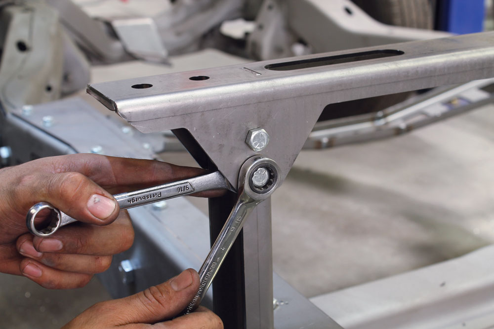
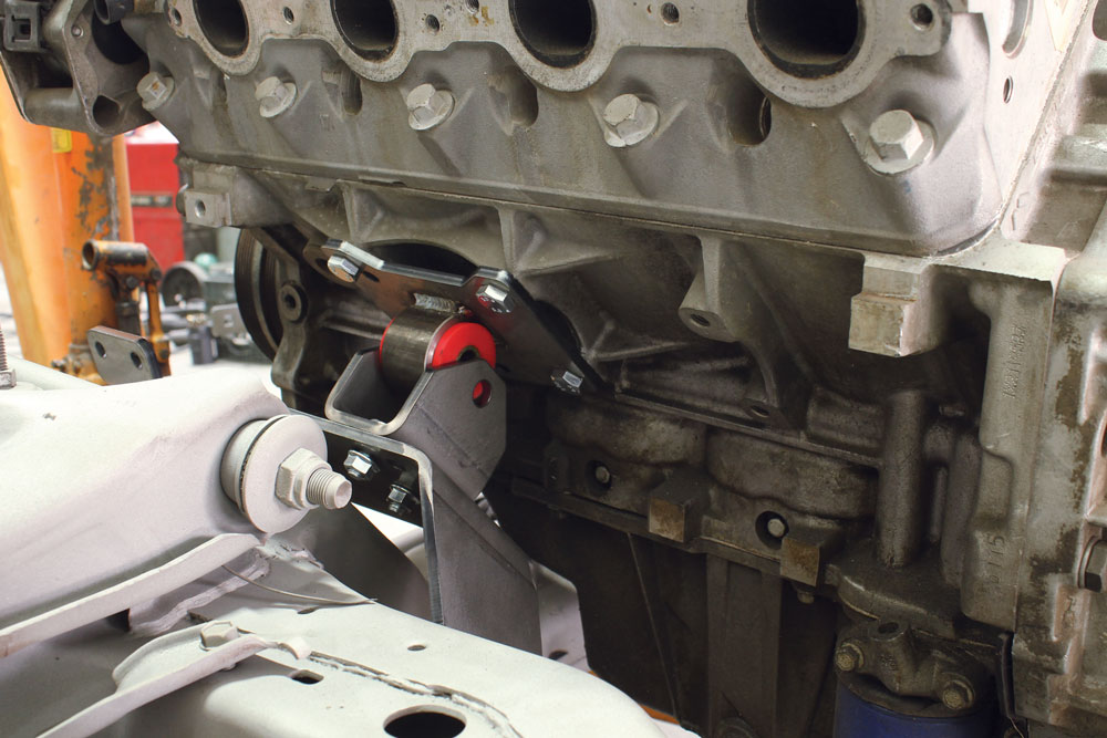
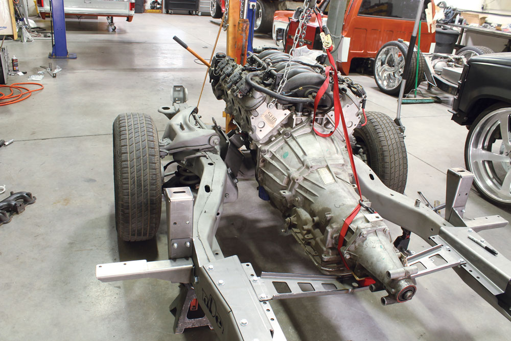
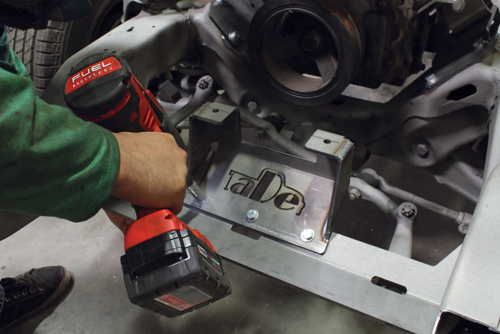
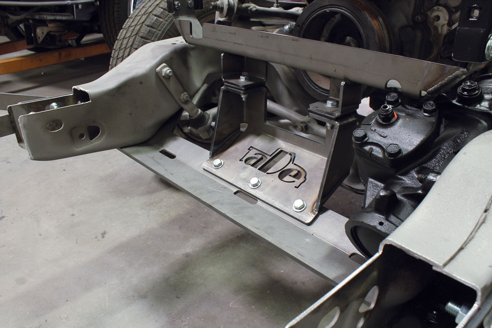
The engine mount is pretty sophisticated. It not only ties into where the factory engine mounts once were, it also uses holes on the rearward lower control arm mount, adding strength to both pieces. Installation on the rearward lower control arm mount is made simple by the use of a threaded plate. The supplied hardware threads into this plate and secures the engine mount plate in its new home.AD-Engineering has several options for engine mounts. We are dropping an LS-based engine in Cindy so we were supplied with these mounts. It appears that these same mounts could also be used with a small-block Chevy. Using the supplied hardware, we attached the engine mounts to the engine block.The final part of the three-piece mount is the U-shaped bracket that will sandwich the engine mount bushing. There are two options for holes when mounting our LS-based engine. We decided to go with the furthest rearward mount in order to get closer to a 50/50 weight bias with the overall chassis. With the engine on a hoist, we slid the new mounts together.The engine and transmission were mounted as one unit and dropped in very easily. Locating the transmission mount in the proper bolt holes per the instructions allowed the supplied transmission mount bushing to fall right in place.
FRONT BUMPER MOUNTS
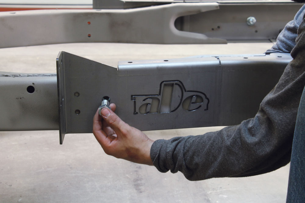
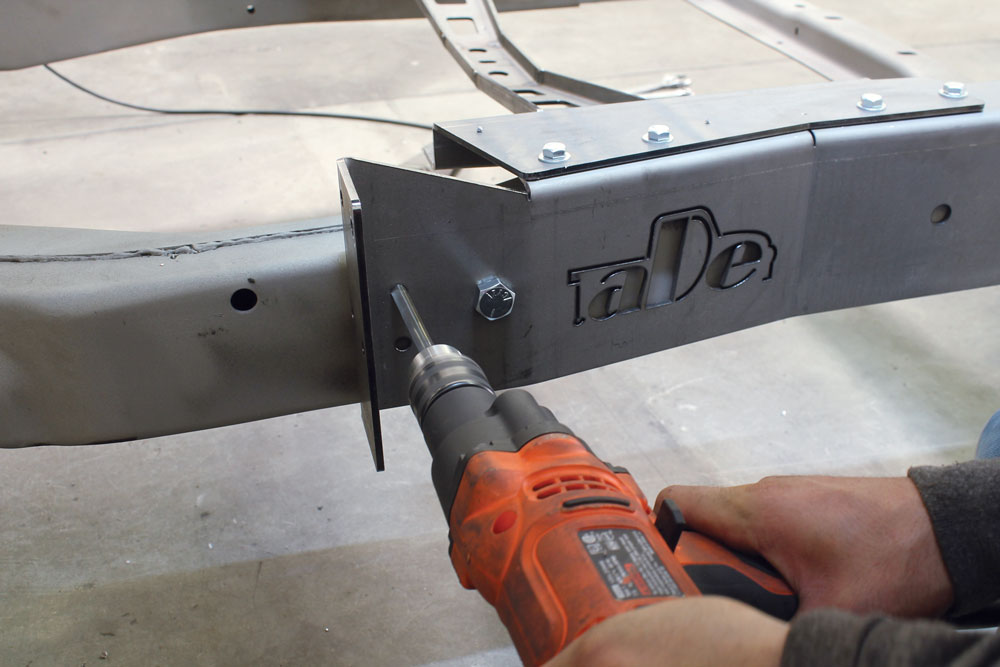
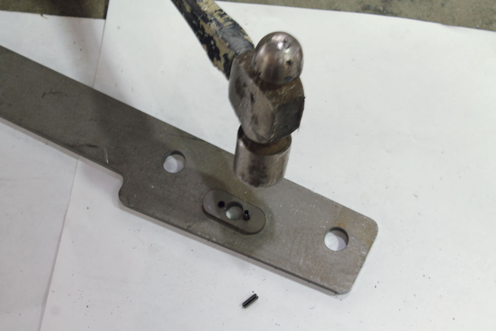
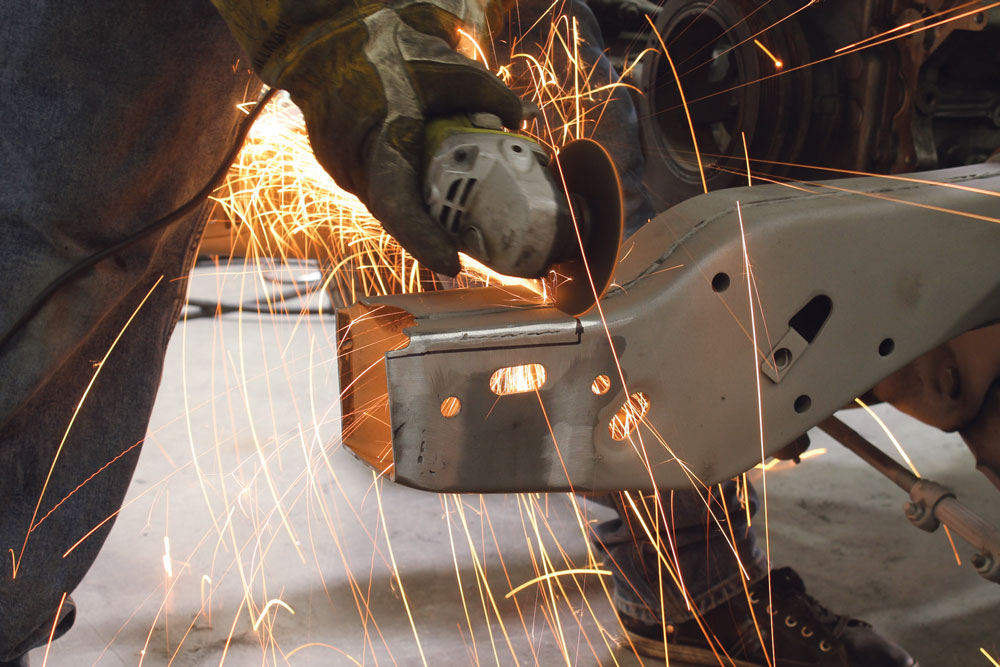
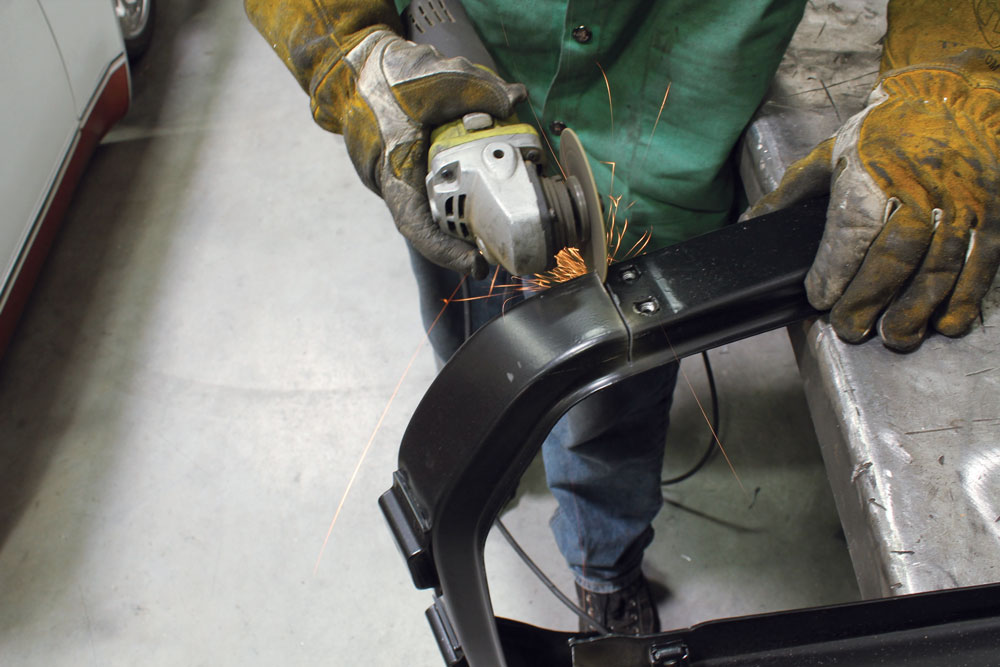
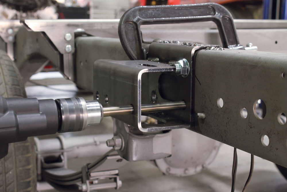
All the way at the front of the truck, we needed to remove more of the factory S-10 mounts. The factory S-10 bumper mounts and radiator support mounts needed to go. A 4.5-inch cut-off wheel on a die grinder was used to remove these two items. We tried to cut right at the welds, which make it easier to clean up the frame.Here’s what it looks like after the mounts are cleaned up with the flap wheel. Make sure you’re not using a rock wheel grinder for this type of clean up because it will leave you with a much rougher and unattractive finish.The first part of the new bumper mounts is another ingenious little idea included with the kit. These pieces fit together snuggly with dowel pins.On the S-10 frame there is a slot, and the mount fits perfectly into it. This locates the bumper mount bracket in perfect alignment with the frame.With the center hole lined up and bolted in place, the outer two bolt holes were drilled and the new hardware was installed.
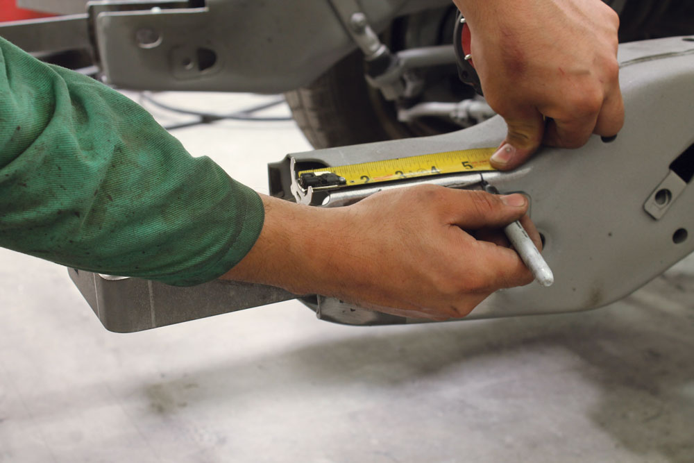
The next step for installing the front bumper mounts is cutting away the top of the frame. Following the instructions, we measured back from the front edge of the frame. Then we used the top of the bumper mount to mark the horizontal cut line and removed the mount to make the cut.To finish this part of the job, we reinstalled the bumper mount with the second part of the mount bolted to the rear most bolt hole.
FRONT CROSS MEMBER
Since we were already at the front of the truck, the new radiator support assembly was tackled next. The first part bolts up using the factory sway bar mount holes.Up next was a piece that’s easily distinguished by the ADE logo. This bolts to the lowest piece with the three supplied bolts and the corresponding hardware.The new radiator support from LMC Truck needed a modification. Actually, the entire bottom of the support is cut off just below the two horizontal bolts.Once we had the modified radiator support mounted to the new lower piece provided with the chassis swap kit, we installed the assembly to the lower mounts. The radiator support is isolated from the lower mounts by urethane bushings.
FINISHING THE REAR
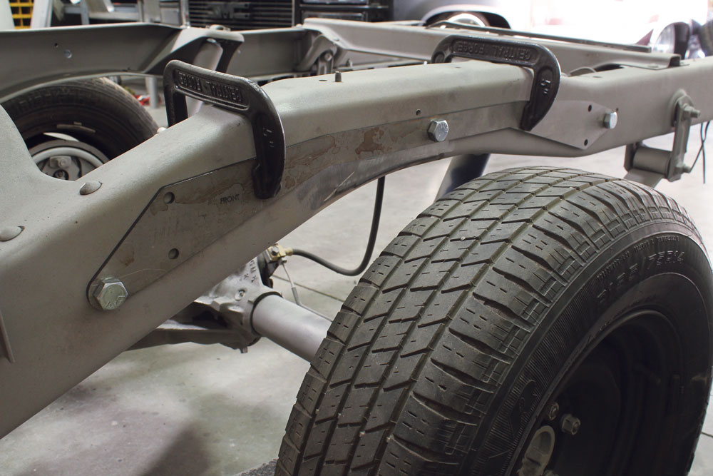
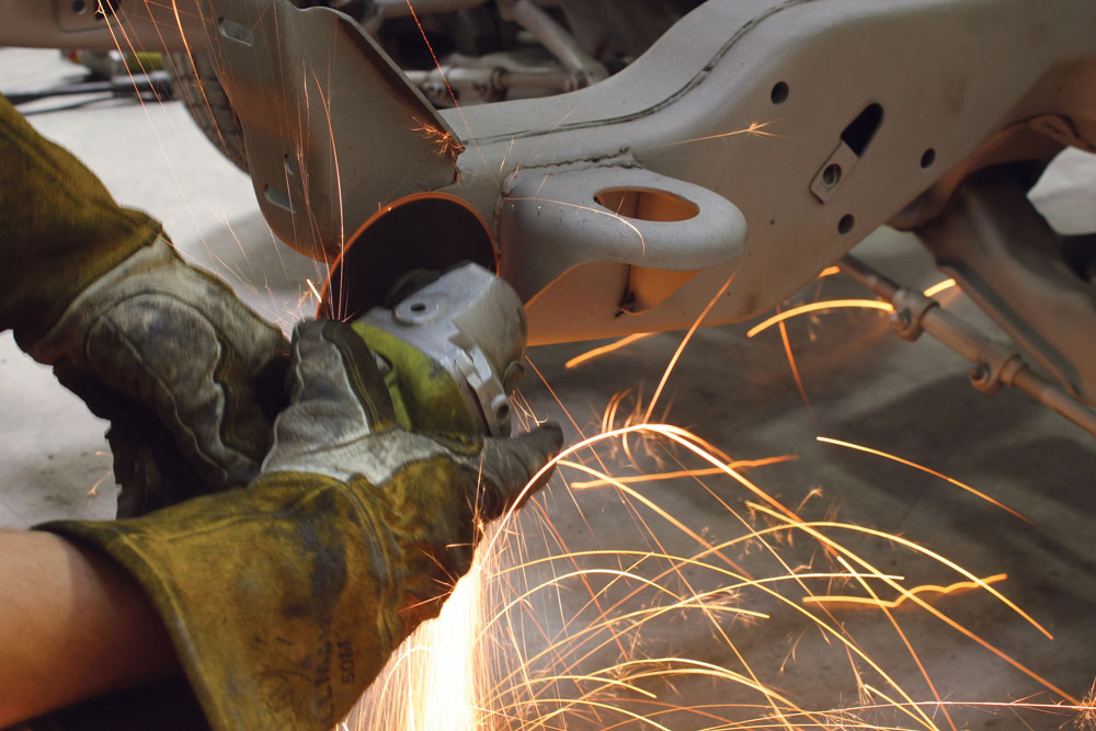
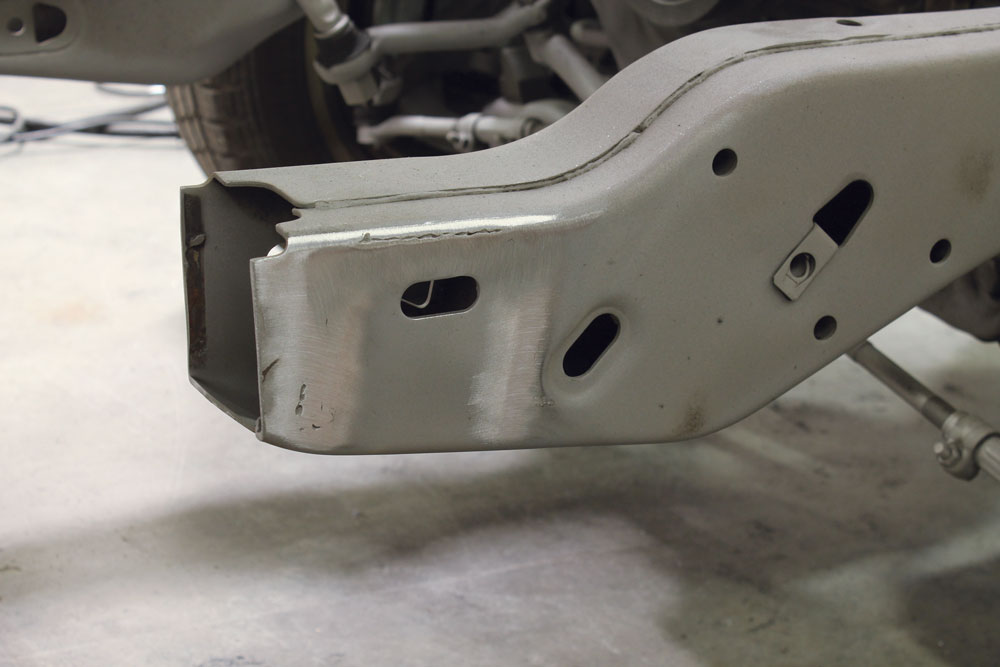
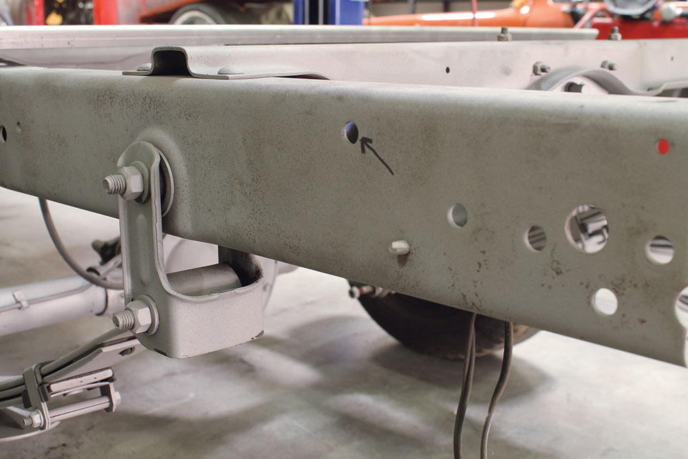
The final modification to the S-10 chassis happened at the rear of the frame. Per the instructions, we located a bolt hole on the side of the frame.We temporarily installed the rear bumper mount using this hole. The new mount is used as a guide for the final holes we need to drill in the S-10 chassis.It also served as a guide for the cut we needed to make in order to remove the tail section of the frame. We removed the mount after marking the rails and used the cut-off wheel to slice through the frame rails.With the frame rail shortened, the mount was reattached with the provided hardware. The outside bolts will act as the attachment point for the factory rear bumper mounts.
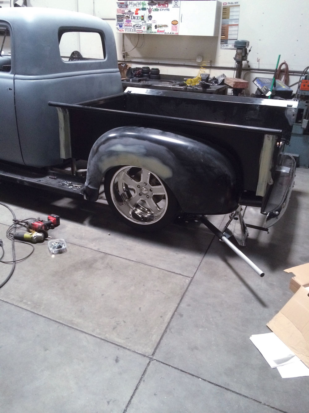
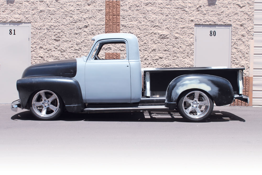
BOLTING ON THE BODY
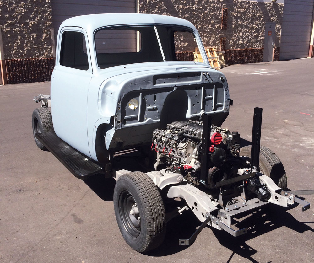
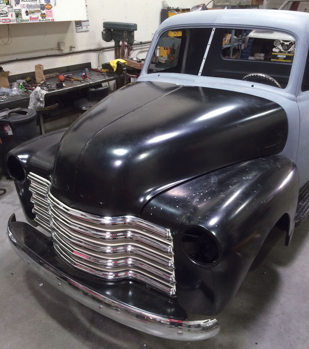
The last pieces included with the kit are for the running boards. We already installed the mounts along the sides of the frame rail, but now we are working on the running boards themselves.This allows for the new plates to slide into the running board. These plates are threaded to accept bolts, which will make mounting the running boards much easier.After only two days of work, one stripping the S-10 frame and one installing the new parts, we had ourselves a new chassis under project Cindy. We rolled the truck outside the shop to get a better look at our quick accomplishment.The following day was spent installing the body panels. Anyone who knows these trucks will vouch for how much work it takes to get all of the front sheet metal installed. It’s not an easy task, but we were able to get things installed and roughly lined up for the body shop to dial in.We set the bed on next and jacked the wheel up in the wheel well to ride height. We wanted to make sure the rear wheel was also centered in the rear fender. It’s amazing how close the wheelbase between a ’49 Chevy pickup and an ’86 Chevy S-10 are. With all of the body panels mocked up and the new suspension installed, Cindy is on her way back to the body shop. I know you’re asking yourself about the new lowered height also; we’ll get to that next time.
FREQUENTLY ASKED QUESTIONS
Why is the S10 frame recommended for a budget-friendly chassis swap?
The S10 frame is a popular choice for chassis swaps for several budget-friendly reasons:
Availability and Compatibility: There are countless S10 trucks on the market. This wide availability means it’s easy to find donor trucks with parts that are interchangeable.
Affordable Spare Parts: Because millions of S10s were produced, parts are not only plentiful but also inexpensive. Whether you need components from a local auto parts store, or prefer to shop online through platforms like eBay or Amazon, you can usually find what you need quickly and at a low cost.
Ease of Sourcing: With the abundance of spare parts for the S10, you often don’t have to wait long for replacements. Many parts are accessible for same-day pickup or delivery, reducing downtime and keeping your project on track.
Overall, these factors make the S10 frame an economical and practical choice for those looking to perform a chassis swap without breaking the bank.
What is the purpose of a chassis swap for 1947-1955 first series AD Chevrolet trucks?
While looking into chassis and suspension upgrades for our ’49 Chevy 3100 Advance Design pickup, we came across Robert Hertz from ADEngineering. There are several options out there for these trucks, from brand-new chassis to weld-in Mustang-II-style front cross members, and some people have even cut the front frame off and clipped them with Camaro or other Chevy-car-style front suspensions.
Robert actually approached us to inform us of a chassis swap kit he produces for the 1947-55 first series pickups and Suburbans. We were definitely intrigued and started talking about using the kit for project Cindy.
A chassis swap can transform your AD truck by enhancing ride quality and driving experience. One popular and budget-friendly option is using the S10 frame. Here’s why it’s a great choice:
Availability: With millions of S10s produced, finding a donor is straightforward.
Cost-Effectiveness: S10 parts are affordable and widely available at auto parts stores, eBay, or Amazon, often with same-day availability.
Versatility: You can reuse many components from the donor, reducing additional expenses.
After exchanging a few emails with Robert, we were sold on the chassis swap kit. The complete kit comes with everything we would need to swap the chassis, engine, transmission, and steering. AD-Engineering has spent a lot of time perfecting the kit, both on the computer-generated plans as well as on vehicles. We selected the options we would need for our project and the parts were soon headed our way.
Before embarking on a frame swap, consider whether a premade kit or custom fabrication suits your needs. Each option has its merits, but the S10 frame stands out for those prioritizing economy without compromising performance. This insight aligns with our goal of achieving an enhanced driving experience while managing costs effectively.
How accessible are parts for the swap?
Parts for the S10 chassis swap are highly accessible. They can be sourced from auto parts stores or online platforms like eBay and Amazon, often with same-day availability, making the process convenient and straightforward.
What are the options for handling a swap?
When considering a swap, there are several approaches: finding a suitable donor vehicle, opting for a premade kit, or fabricating your own parts. Experience with different suspension setups, like Mustang II crossmembers or Camaro subframes, can guide your choice based on budget and desired outcomes.
Which chassis is recommended for a swap and why?
The S10 frame is highly recommended for a swap. This recommendation is based on the widespread availability of donor vehicles, the ability to repurpose many components, and the overall low cost associated with S10 parts.
Why perform a chassis swap?
A chassis swap can significantly enhance the ride quality and driving experience of a vehicle. It is also a cost-effective solution due to the potential savings from using readily available and affordable donor parts.
Why is it advantageous to replace or install these components before setting the body on the frame?
Installing these components is more convenient when the body is not yet mounted, as it provides easier access to the necessary areas.
What specific components should be replaced or installed before setting the truck body on the frame?
Before placing the body on the frame, it’s advisable to address components like brake lines, shocks, front steering parts, lowering springs, spindles, the gas tank, and fuel lines.
What are the benefits of using these aftermarket kits?
These kits are designed to be bolt-on, simplifying the process by eliminating much of the guesswork and requiring only basic skills and tools.
What are the advantages of using a regular cab longbed S10 as a donor truck?
The kit from ADEngineering is designed to work with a standard cab long bed S-10 chassis. The 1982-93 model years are a bit easier to perform the swap with, but the 1994-2005 will work just fine as well. The difference between the two model years is that the earlier versions are not boxed in as far back, making it easier to get to the new bolt locations.
When considering a donor truck, the regular cab longbed S10 stands out for several reasons:
Minimal Modifications Required: With this configuration, there’s no need to shorten the vehicle or cut and re-weld the donor frame. This significantly simplifies the process, especially for those who prefer avoiding extensive modifications.
Ease of Use: Most enthusiasts appreciate the straightforward nature of using a regular cab longbed, as it minimizes the technical skills needed for the swap.
By choosing a regular cab longbed S10, you not only streamline your project but also enjoy the flexibility of working with a vehicle that aligns seamlessly with the kit’s requirements. This ensures a smoother transition from donor to finished product, allowing for a more efficient and less stressful build process.
Why is a regular cab longbed S10 advantageous as a donor?
Opting for a regular cab longbed S10 simplifies the process because it fits without needing significant alterations, making it an ideal choice for straightforward projects.
What is the estimated time required to complete the frame swap?
With focused work over two days and the help of a couple of friends, the frame swap can be accomplished within a weekend.
How many people are needed to mount the truck body onto the frame?
Typically, the task requires two people. This ensures that there is adequate assistance for lifting and aligning the components accurately.
What equipment is needed to lift and mount the truck body onto the frame?
To effectively lift and position the truck body onto the frame, you’ll need equipment like a hoist, a lift, or a forklift. These tools are essential for handling the heavy components safely.
What preparations should be made before mounting the body onto the frame?
Prior to placing the body onto the frame, ensure that you have replaced critical components such as brake lines, shocks, and front steering parts. Additionally, install lowering springs, spindles, the gas tank, and fuel lines to make the process smoother.
Which kits are recommended for mounting the old truck body onto the new S10 frame?
For a seamless installation, consider using either the Henry Panza kit or the code 504 kits. These are designed to be straightforward bolt-on solutions, reducing the complexity of the project.
Is it necessary to replace all parts during a chassis swap?
It is not mandatory to replace all parts during a chassis swap. While a complete replacement is common, the choice of which components to keep or discard is up to you, allowing for a personalized approach based on your needs and preferences.
What are the key considerations when selecting a donor truck?
Here’s the donor truck. This 1986 standard cab long-bed S-10 was the perfect candidate for our chassis swap. We picked it up for $450, and it was still running and driving. It did have a blown head gasket, but that didn’t stop us from attempting to completely blow up the engine with a nice burnout.
Why This Truck Was the Ideal Choice
When selecting a donor truck, there are several key considerations to keep in mind:
Configuration: The best choice is any year S10 that is a regular cab long bed. This configuration is ideal because it requires minimal modification, sparing you from cutting the donor frame in half and rewelding it.
Cost: Expect to pay between $300 and $700 for a frame or complete truck. We got ours for $450, which is within this range.
Frame Modifications: While you still need to do some trimming on the long-bed frame, such as cutting about 6 inches at the front and rear, this is manageable compared to more extensive modifications.
Model Simplicity: Older models, often referred to as “square bodies,” are advantageous because they lack complex features like ABS or wheel speed sensors, making the stripping process more straightforward.
Condition: Always check for frame damage to avoid the headache of straightening a compromised frame. Avoid trucks that have been wrecked.
What is the cost range for acquiring a donor truck?
Expect to spend between $300 and $700 for either a frame or a complete truck, allowing for budgeting flexibility.
What is the ideal configuration for a donor truck?
An S10 regular cab with a long bed is considered the best option because it requires minimal frame alterations.
What tools can be used for dismantling a donor truck?
Tools such as reciprocating saws, grinding wheels, plasma cutters, and torches are commonly used for dismantling.
Why is the S10 regular cab longbed recommended?
This specific configuration is recommended because it minimizes the need for extensive modifications, like cutting and welding the frame, which can be complex for those unfamiliar with such tasks.
What type of truck should I look for as a donor?
The ideal donor truck is any year S10 that has a regular cab and a long bed, as this configuration requires the least amount of modification for a chassis swap.
What are the experiences of those who have completed an S10 frame swap on their vehicles?
Experiences with Completing an S10 Frame Swap
Completing an S10 frame swap can be a rewarding yet demanding project. Those who have gone through the process often highlight the considerable effort involved to achieve a satisfactory result. Unlike some online listings that suggest a “quick and easy” conversion, the truth is far more complex.
Challenges and Considerations
Time and Effort: Many who undertake this project note that it’s not straightforward. It requires meticulous planning and execution to get everything “just right.”
Fabrication Skills Required: You’ll likely need design, fabrication, and welding skills to address the various adjustments that arise. This involves fitting components like the cab, front fenders, and more, onto the new frame.
Component Compatibility: There’s the task of selecting compatible parts, such as choosing the right gas tank, radiator, and configuring the exhaust system around the S10 steering box.
Alternative Approaches
Some enthusiasts suggest sticking with the stock frame and installing a Mustang II cross member for an easier build. Additionally, using aftermarket rear spring kits to mount a different rear end can streamline the process, potentially wrapping up the chassis work over a weekend.
The Fun Factor
Despite the challenges, there is a consensus that the project should be enjoyable. If it’s not, it might be a sign you’re in the wrong hobby. The sense of accomplishment once completed is often well worth the effort invested.
Whether you choose to tackle an S10 frame swap or explore other methods, the journey can be as satisfying as the destination.
What are the benefits of keeping the original frame versus performing an S10 frame swap?
Benefits of Keeping the Original Frame vs. Performing an S10 Frame Swap
Keeping the Original Frame
Ease of Assembly: By retaining the original frame, you sidestep the complex process of re-mounting components like the cab, front fenders, radiator core support, bumpers, running boards, and bed. This can save time and reduce the need for extensive modifications or adjustments.
Fewer Compatibility Issues: Sticking with the original frame eliminates the need to select compatible parts such as gas tanks or radiators that fit specific aftermarket frames. This makes it easier to work with existing parts and reduces the likelihood of unforeseen issues.
Quick Installation: Using the original chassis could streamline your project timeline, potentially enabling you to complete the chassis in a much shorter period, like over a weekend with the right parts.
Performing an S10 Frame Swap
Modern Performance Enhancements: An S10 frame swap can provide modern performance upgrades, such as improved suspension systems, that might not be easily achievable with the original frame.
Potential for Customization: While it may require fabrication skills, the flexibility of an S10 swap allows for extensive customization, from the positioning of components to the integration of new technology.
Sturdier Chassis: The S10 frame can offer a stronger foundation, potentially providing a more durable ride, especially if you plan to add power or carry heavier loads.
In conclusion, the choice between maintaining the original frame or opting for an S10 frame swap depends largely on your project goals and skill level. Keeping the original may be simpler and quicker, while a frame swap offers modern benefits but demands more expertise and time.
What are the advantages of using a Mustang II front end on a vintage truck?
Advantages of Using a Mustang II Front End on a Vintage Truck
Upgrading a vintage truck with a Mustang II front end can transform both its performance and ease of maintenance. Here’s why enthusiasts often choose this setup:
Enhanced Handling and Stability
Modern Suspension: The Mustang II front end offers a more sophisticated suspension system compared to the original vintage setup, providing improved handling and a smoother ride.
Better Control: With better weight distribution and independent suspension, expect superior control—especially during cornering.
Simplified Installation and Customization
Retain Original Frame: By integrating the Mustang II cross member onto the stock frame, there’s no need for extensive modifications. This approach preserves the truck’s original structure, simplifying the installation process.
Easy Component Mounting: Keeping the original frame allows for straightforward mounting of essential components like the cab, fenders, and bumpers. You avoid the headaches of customizing mounts for these parts.
Flexibility for Further Upgrades
Options for Rear Suspension: Pairing this front end with aftermarket rear suspension kits, such as those compatible with Camaro rear ends, can complete your chassis overhaul in just a weekend.
Future Modifications: Retaining the stock frame makes future upgrades more accessible, offering a flexible starting point for additional modifications or custom fabrications.
Fun and Skill Development
Skill Enhancement: While the installation might require some design and fabrication skills, it’s an opportunity to improve these talents.
Enjoyable Experience: Tinkering with a project like this should be enjoyable. If the process becomes too frustrating, it may be time to reassess your approach or project choice.
Upgrading to a Mustang II front end on your vintage truck can be an exciting journey, blending classic aesthetics with modern capabilities.
What is the potential value of a complete rolling frame with a good running engine and rebuilt brake system?
The value of a complete rolling frame with a good running engine and a rebuilt brake system can vary, but generally, it may be worth a few hundred to a few thousand dollars depending on several factors.
Factors Influencing Value:
Condition:
Engine: A well-maintained, running engine significantly boosts value. Ensure it operates smoothly without issues.
Brake System: A rebuilt brake system indicates reliability and safety, which are attractive to buyers.
Make and Model:
Specific models from popular manufacturers can demand higher prices due to their desirability and collectability.
Market Demand:
If there’s a high demand for the model in question, or if it’s rare, the frame could fetch higher offers.
Completeness:
If the frame includes additional components such as the drivetrain, suspension, or electronics, the value increases.
Potential Evaluation:
Standard Models: Typically range from $500-$1,500.
Rare or High-Demand Models: Can exceed $2,000, especially if all components are in excellent condition.
In summary, while a basic offer might start reasonably low, potential buyers, particularly enthusiasts, might be willing to pay a premium for a desirable frame that promises minimal restoration effort.
What are the available resources or guides for someone undertaking an S10 frame swap for the first time?
“After exchanging a few emails with Robert, we were sold on the chassis swap kit. The complete kit comes with everything we would need to swap the chassis, engine, transmission, and steering. AD-Engineering has spent a lot of time perfecting the kit, both on the computer-generated plans as well as on vehicles. We selected the options we would need for our project and the parts were soon headed our way.
For those new to an S10 frame swap, it’s essential to understand that this isn’t a weekend project. However, with the right resources and planning, it can be incredibly rewarding. Here’s what you need to know:
Step-by-Step Guidance: We received detailed instructions, complete with step-by-step pictures and tips. These proved invaluable as they highlighted crucial details and common pitfalls to avoid.
Preparation is Key: Before you begin, ensure every part needed is organized and ready. With advance planning, you can efficiently mount the cab, box, front clip, and steering onto the S10 frame in just one day.
Component Choices: There are options for different rear axles, like the Explorer 8.8, which is widely available and often a better choice than the increasingly rare Camaro/Firebird. The kit includes guidance on re-drilling bolt patterns to ensure everything aligns perfectly.
Finishing Touches: Even with the main components in place, expect to spend a couple of months on finishing tasks. This includes the electrical setup, fuel tank mounting, brake installation, and more. Patience and attention to detail are crucial here.
With this comprehensive approach, the swap process becomes much more manageable, transforming your project from a daunting task into an achievable goal.”
What remaining tasks will need to be completed after the initial swap?
Post-swap tasks involve electrical work, fuel tank mounting, brakes, radiator relocation, engine and transmission installation, shift linkage, and running fuel and brake lines, all of which could take a few months to finalize.
What modifications might be necessary?
Modifications include re-drilling bolt patterns to ensure compatibility between the rear axle and front components, depending on selected parts.
What options are available for specific components?
Options include frame blasting and painting, and choices for rear axles such as the Explorer 8.8 or the Camaro/Firebird, with considerations for lug patterns and availability.
How should one prepare for the swap?
Preparation involves organizing all necessary parts ahead of time to efficiently mount the AD cab, box, front clip, and steering onto the S10 frame, ideally completing this in a day with thorough pre-arrangement.
What kind of guidance is available for first-timers?
First-timers can receive step-by-step guidance, including pictures and tips, to help navigate the complexities of an S10 frame swap.
What technical skills are necessary for a successful S10 frame swap?
The swap demands a range of technical skills, including design, fabrication, and welding expertise. These skills are essential to address the customizations and modifications required throughout the process.
What additional modifications and decisions are necessary during an S10 frame swap?
Decisions need to be made regarding the choice of gas tank and radiator, as well as figuring out how to clear the S10 steering box and route the exhaust effectively. These choices are crucial for the swap’s success.
What compatibility issues may arise with an S10 frame swap?
Compatibility issues can include fitting challenges with the cab, front fenders, radiator core support, front and rear bumpers, running boards, and the bed. These elements may not seamlessly align with the S10 frame, requiring additional modifications.
What are some common pitfalls or misconceptions about S10 frame swap projects?
Many projects are marketed as “almost done” or “easy to finish,” but in reality, they can be far from complete. This highlights a common misconception about the ease of completing such swaps.
How difficult and effort-intensive is an S10 frame swap?
An S10 frame swap is notably labor-intensive and requires a lot of work to achieve the desired outcome. It’s not a quick or simple task, demanding significant attention to detail and patience.
What are some alternative options to an S10 frame swap for improving a vintage truck’s chassis?
While looking into chassis and suspension upgrades for our ’49 Chevy 3100 Advance Design pickup, we came across Robert Hertz from ADEngineering. There are several options out there for these trucks, from brand-new chassis to weld-in Mustang-II-style front cross members, and some people have even cut the front frame off and clipped them with Camaro or other Chevy-car-style front suspensions.
For those exploring alternatives to the popular S10 frame swap, it’s worth considering maintaining the original stock frame. This option allows for modifications such as an Independent Front Suspension (IFS) or an open rear swap, which can be more straightforward than a full chassis replacement. The Mustang-II cross member is a standout choice, offering a seamless way to upgrade the front suspension while preserving the truck’s authenticity.
Additionally, installing an aftermarket rear leaf spring kit to accommodate a Camaro rear end can efficiently complete the chassis transformation in a weekend. This approach not only simplifies the process but also eliminates the need to address complex issues like mounting the cab, front fenders, and other components that may arise with an S10 frame swap.
While the S10 swap remains a popular choice, it’s important to be aware of the design, fabrication, and welding skills required. This swap can present challenges such as deciding on a suitable gas tank, radiator compatibility, and exhaust routing.
Ultimately, the path you choose should align with your skills and enthusiasm for the project, ensuring that the journey is as enjoyable as the destination. After all, if you’re not having fun, you might be in the wrong hobby.
We use cookies to enhance your browsing experience, serve personalized ads or content, and analyze our traffic. By clicking "Accept All", you consent to our use of cookies. Visit our Cookie Policy for more info.
 JEREMY RICE
.
August 20, 2020
.
Editor
JEREMY RICE
.
August 20, 2020
.
Editor


Share Link